
Description
Hard-Numbers: Technical Specificiations
- Supply Voltage: 24 VDC (sourced from EPSM module)
- Analog Output Channels: 8 isolated channels (4-20mA or 0-10VDC configurable)
- Resolution: 16-bit (65,536 steps per range)
- Accuracy: ±0.1% of full scale
- Load Resistance: Max 750 Ohms (for 4-20mA loops)
- Update Rate: 50 ms (output refresh)
- Isolation Rating: 1500V AC (channel-to-channel and channel-to-backplane)
- Operating Temperature: -40°C to +85°C
- Mounting Location: Exciter Power Backplane Rack (EPBP)
- Diagnostic LEDs: Power, Comm Active, Channel Fault (Per Channel)
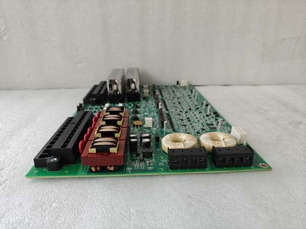
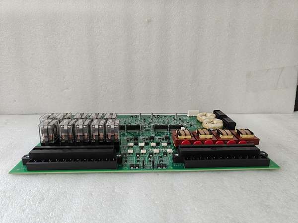
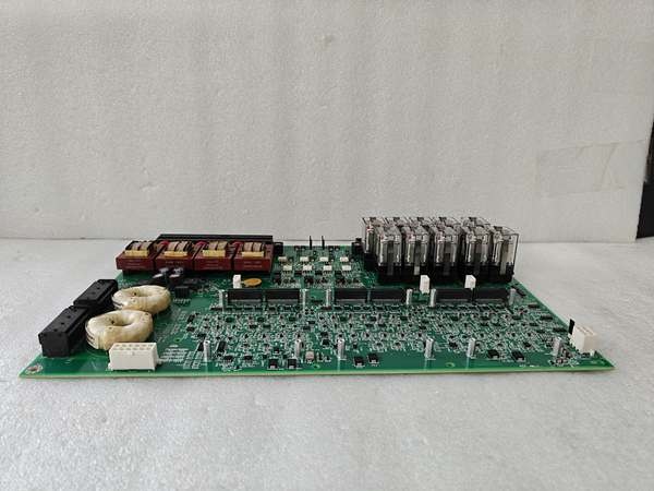
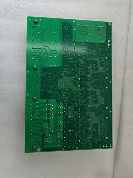
GE IS200ESYSH1A
The Real-World Problem It Solves
You’re standing in the control room watching the HMI trend flatline because the plant DCS is screaming “Generator Field Current Loss.” The raw digital data from the DSPX is useless to the plant’s 1980s-era DCS, which only speaks analog 4-20mA. You need a translator that can take the high-speed digital excitation data and spit out rock-solid analog signals without drifting or dropping out. This ESYS board eliminates that headache. It acts as the bridge between your high-tech excitation rack and the plant’s legacy monitoring infrastructure, keeping the operators happy and the data flowing.
Where you’ll typically find it:
- EX2100/EX2100e Exciter Cabinets: Mounted on the EPBP backplane, providing analog telemetry to the plant-wide DCS or historian.
- Legacy Plant Retrofits: Feeding critical excitation parameters (Field V/I, Exciter Temp) into obsolete control systems that lack digital communication ports.
- Remote Monitoring Skids: Transmitting generator health data via 4-20mA loops over long distances to centralized control rooms.
It turns an incompatible, data-siloed excitation system into a fully transparent, analog-integrated asset for plant operations.
Hardware Architecture & Under-the-Hood Logic
This isn’t a simple resistor ladder; it’s a precision digital-to-analog converter (DAC) with heavy-duty industrial hardening. It lives on the EPBP backplane, acting as the voice of the excitation system to the outside world. The “H1A” suffix indicates optimized trace routing and enhanced component selection for high-accuracy deployments.
- Digital Data Acquisition: The ESYS pulls real-time excitation parameters (Generator Voltage, Field Current, Exciter Temperature) from the DSPX processor via the high-speed ERBP backplane bus.
- High-Resolution DAC Conversion: An onboard 16-bit Digital-to-Analog Converter processes the digital data. It scales the values according to the configuration and generates a highly accurate analog voltage or current.
- Galvanic Output Isolation & Driving: Each of the 8 output channels is individually galvanically isolated (1500V AC). A precision op-amp and current-boosting transistor drive the external 4-20mA loop or 0-10VDC signal, ensuring the field wiring noise doesn’t bleed back into the excitation rack.
- Loop Health Monitoring: Integrated comparators constantly watch the voltage drop across the output terminals. If a wire breaks or a DCS input card fails (open circuit), the channel’s Fault LED illuminates, and the board reports the anomaly to the DSPX via the backplane.
GE IS200ESYSH1A
Field Service Pitfalls: What Rookies Get Wrong
Creating Ground Loops with Improper Shield Termination
A rookie lands the shielded twisted-pair cable from the DCS to the ESYS terminal block. He grounds the shield at the DCS end and also at the ESYS end. This creates a massive ground loop. The 60Hz hum from the plant earth grid induces phantom currents, causing the “Generator Field Current” to swing wildly between 2500A and 3000A on the operator’s screen.
- Field Rule: Implement single-point grounding for all analog shields. Terminate the shield drain wire at the DCS input card end only. Leave the shield floating and insulated at the ESYS terminal strip. A ground loop is a guaranteed ticket to a wild-goose chase.
Exceeding the Maximum Loop Resistance (750 Ohms)
A junior engineer designs the DCS interface and runs 2000 feet of 22 AWG instrumentation wire from the ESYS to the control room. The total loop resistance hits 950 Ohms. When the ESYS tries to drive 20mA, the voltage drop across the wire eats up all the headroom, capping the actual current at 14mA. The DCS reads “70% Field Current” when the rotor is actually fully excited.
- Quick Fix: Before landing the first wire, calculate the total loop resistance (Wire resistance + DCS input resistance). Use a loop calibrator to verify the ESYS can drive a full 20mA into the actual field wiring. If the resistance is too high, you must use heavier gauge wire (e.g., 18 AWG or larger).
Skipping the Cold-Junction Offset Calibration
A mechanic replaces a failed ESYS and skips the calibration routine. The onboard DAC’s voltage reference has a 0.5% tolerance variance from the factory spec. The ESYS outputs 4.05mA at zero scale and 20.1mA at full scale. The DCS interprets this as a permanent 1% field current error, triggering a “Field Undercurrent” alarm during synchronization.
- Field Rule: After installing any ESYS, perform the zero/full-scale calibration using ToolboxST. Verify the module’s current output against a calibrated milliamp clamp at 4mA and 20mA. A 1% offset in an excitation feedback loop can cause massive AVR instability.
Commercial Availability & Pricing Note
Please note: The listed price is for reference only and is not binding. Final pricing and terms are subject to negotiation based on current market conditions and availability.


