
Description
Hard-Numbers: Technical Specificiations
- Input Voltage: 125 VDC (sourced from station battery bus)
- Gate Drive Output: Up to ±20V (configurable via jumpers)
- Gate Drive Current: Peak > 3.0 Amps
- Response Time: < 5 ms (logic command to gate pulse)
- Operating Temperature: -20°C to +60°C
- Isolation Rating: 2500V RMS input-to-output
- Mounting Location: Exciter Power Backplane Rack (EPBP)
- Diagnostic LEDs: Power, Static Switch Active, Fan Status, Line Filter, Fault
- Communication Interface: Backplane (ERIB Bus to DSPX)
The Real-World Problem It Solves
You’re staring at a 9FA gas turbine as it undergoes a planned shutdown. Suddenly, the SCR bridge short-circuits, dumping a massive inductive kickback into the rotor winding. Without a way to instantly bypass the bridge and clamp the field current to a safe DC level, you’re looking at a melted stator and a multi-million dollar rotor rewind. You need a module that can hear the distress call from the DSPX and literally snap the static switch (thyristor or GTO) into action in the blink of an eye. This ERSC board eliminates that nightmare. It acts as the ultimate circuit-breaker-for-your-field, ensuring a hair-trigger transition to emergency DC excitation or a safe discharge path.
Where you’ll typically find it:
- EX2100/EX2100e Exciter Cabinets: Mounted in the EPBP rack, interfacing directly with the high-current static switching device.
- Large Combined-Cycle & Nuclear Plants: Protecting multi-hundred megawatt generators during severe grid disturbances and system trips.
- Retrofit Projects: Replacing clunky, slow-acting electromechanical contactors with deterministic, solid-state switching logic.
It turns a potential rotor-killing inductive voltage spike into a controlled, sub-5ms static switch engagement.
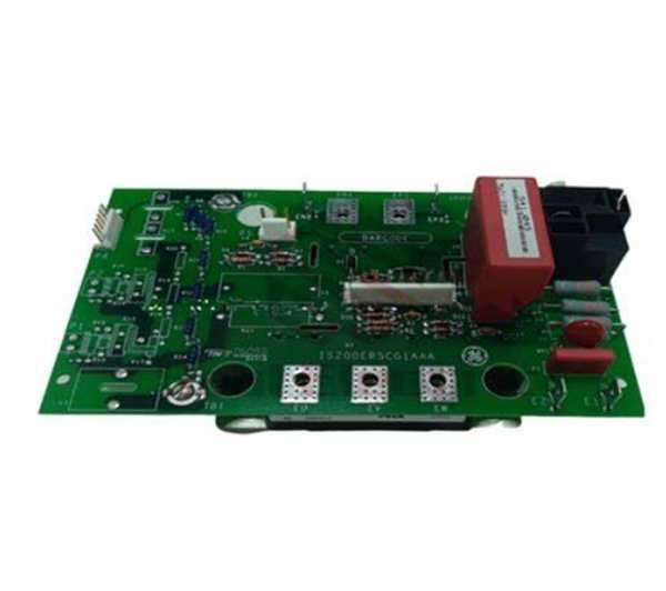
GE IS200ERSCG1A
Hardware Architecture & Under-the-Hood Logic
This isn’t just another passive relay driver; it’s a high-speed pulse generator built to survive the electrical carnage of a failing power bridge. It lives on the EPBP backplane, acting as the lightning-fast courier between the DSPX processor’s software brain and the brute force of the static switch. The “G1A” suffix indicates optimized trace routing and enhanced component selection for rapid-fire environments.
- Logic Command Acquisition: The ERSC listens intently over the backplane (ERIB Bus) for a “Switch Now!” command from the DSPX processor. This could be triggered by a bridge short, an overcurrent event, or a deliberate redundancy switch.
- High-Speed Pulse Amplification: Upon receiving the command, an onboard high-current driver instantly amplifies a low-voltage logic signal into a punishing ±20V gate pulse. This pulse is strong enough to pierce the gate-cathode junction of the static switch device in microseconds.
- Static Switch Firing: The amplified pulse is routed through heavy-duty terminal blocks to the gate of the static switch (usually a large thyristor or GTO). The switch closes, creating a low-impedance path that diverts the field current away from the damaged SCR bridge and onto the standby DC bus or discharge resistor.
- Real-Time Health Monitoring: Integrated comparators watch the output stage for signs of a shorted gate or an open circuit. If the static switch fails to fire, the board instantly latches a hardware fault and alerts the DSPX, preventing a blind handoff that could blow the rotor.
Field Service Pitfalls: What Rookies Get Wrong
Reversing the Gate Drive Polarity to the Static Switch
A rookie is landing the heavy-gauge cables from the ERSC to the static switch gate. He gets cocky and doesn’t check the schematic. He reverses the positive and negative gate leads. He energizes the system, and the static switch remains stubbornly open. During the next load rejection, the inductive kickback has nowhere to go, frying the SCR bridge and cooking the rotor winding.
- Field Rule: Always use a multimeter to verify gate lead polarity against the static switch manufacturer’s datasheet beforeapplying power. A reversed gate lead is a guaranteed recipe for a catastrophic rotor failure.
Using Undersized Wire for the 125VDC Input Lugs
To snake through a cramped cable tray, a junior engineer reuses some leftover #18 AWG wire for the 125VDC input from the station battery. During a peak load ramp, the ERSC draws heavy current to fire the static switch. The undersized wire heats up to 120°C, melts the insulation, and creates a short circuit that blows the plant’s entire 125VDC distribution breaker.
- Quick Fix: Use minimum #12 AWG (4mm²) stranded copper wire for the 125VDC input. Crimp on heavy-duty compression lugs and torque them down to 15 lb-in. Slap some anti-oxidizing paste on the lugs to fight off corrosion creep. This board pulls real power—don’t starve it with skinny wire.
Ignoring the Onboard Snubber and RC Absorption Circuit
A mechanic replaces a failed ERSC. He notices a small, charred-looking resistor-capacitor network soldered near the output terminals. Thinking it’s just “extra parts,” he snips them off to make room for his zip-ties. The next time the static switch fires, the sudden interruption of the high-inductive field current creates a lethal voltage transient that arcs across the ERSC’s output stage, vaporizing the board.
- Field Rule: Never alter or remove the snubber/RC absorption components on the ERSC’s output terminals. These are not optional extras; they are sacrificial lambs designed to absorb the voltage spikes generated when the static switch opens or closes. Leave them alone.
Commercial Availability & Pricing Note
Please note: The listed price is for reference only and is not binding. Final pricing and terms are subject to negotiation based on current market conditions and availability.


