
Description
Hard-Numbers: Technical Specifications
-
Output Current: 20A DC continuous, 30A DC for 10 seconds (overload)
-
IGBT Configuration: Six IGBTs in 3-phase inverter bridge (integrated power module)
-
PWM Frequency: Not specified (typically 2-8 kHz for excitation systems)
-
Input Power: Rectified AC, station DC battery (125V/250V), or combination
-
Field Discharge: IGBT-controlled discharge to external dynamic discharge (DD) resistor
-
Soft Charge: Relay K3 bypasses DC link charging resistor for controlled capacitor pre-charge
-
Operating Mode: Simplex or redundant (dual regulator systems linked to single field)
-
Control Interface: Gate pulse connections from ERBP/EGPA boards (12 soldered gate leads, 4 bolted power connections)
-
Dimensions: 101.63 mm × 152.41 mm (4″ × 6″)
- Weight: 0.47 kg (1.04 lbs)
-
Mounting: VME-style card edge with retention screws
-
Related Boards: ERRR (Exciter Regulator Redundant Relay), ERDD (Exciter Regulator Dynamic Discharge), ERBP (Exciter Regulator Backplane)
The Real-World Problem It Solves
You know the stakes: a 500MW generator loses excitation because the old rotating exciter brushes failed, or a field flash event damages the excitation transformer. The IS200ERSCG1A eliminates these mechanical nightmares with solid-state IGBT power conversion—no brushes, no commutators, no rotating parts. It converts rectified AC or battery DC into precisely controlled PWM field current, while providing fast field discharge through IGBT switching rather than mechanical contactors. The soft-charge relay prevents inrush current from destroying DC link capacitors on startup.
Where you’ll typically find it:
-
EX2100 excitation cabinets for Frame 7/9 gas turbines and steam turbines in combined-cycle plants
-
Hydro generator static excitation systems in dam powerhouses
-
Emergency backup excitation systems using station battery power
Bottom line: It replaces mechanical rotating exciters with solid-state electronics, giving you precise digital control of generator field current with microsecond-level response for stability and protection.

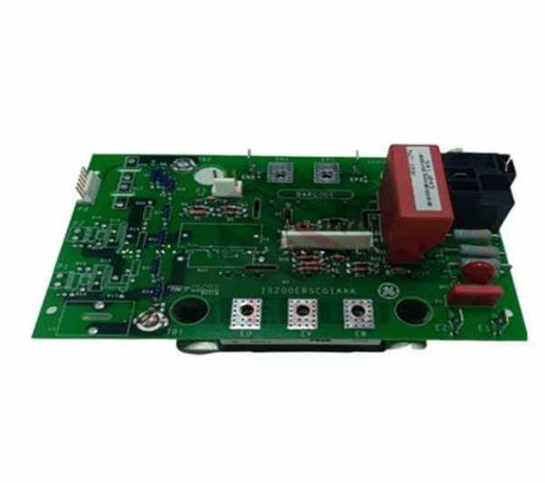
GE IS200ERSCG1A
Hardware Architecture & Under-the-Hood Logic
The IS200ERSCG1A is a power electronics board, not a control computer. It sits in the power stage of the EX2100 system, receiving gate pulse commands from the control boards (EGPA/EHPAG) and switching high-current IGBTs to generate the DC field output. The board handles raw power—20+ amps at hundreds of volts—not logic signals.
Signal flow and power conversion logic:
-
DC Link Charging: On initial power-up, the K3 relay is open; current flows through a charging resistor to slowly charge the DC link capacitors (prevents inrush)
-
Soft Charge Completion: Once capacitors reach threshold voltage, K3 relay closes to bypass the charging resistor, providing low-impedance power path
-
PWM Generation: Control boards send gate pulse signals to the IGBT module; two of six IGBTs switch to create PWM DC output for the generator field
-
Field Discharge: On excitation trip or emergency shutdown, a third IGBT switches to discharge DC link energy into the external dynamic discharge resistor (prevents field collapse voltage spikes)
-
Redundancy Switching: In redundant systems, the ESEL (Exciter Selector) board coordinates handoff between primary and backup ERSC boards without breaking field current
Field Service Pitfalls: What Rookies Get Wrong
Treating This Like a Control Board Rookies see “Exciter Regulator” in the name and think this is the brains of the system. It’s not—it’s the muscle. The IS200ERSCG1A handles lethal voltages and currents (hundreds of volts, 20+ amps). There are no DIP switches to configure, no firmware to flash, no LEDs to watch. If you probe this board live without proper PPE and high-voltage training, you’ll find out why they call it “static” converter—because you’ll be statically dead.
Field Rule: This board is NOT field-repairable at the component level. The IGBT module is soldered/bolted with specialized thermal interface materials. If the board fails, replace the entire unit. Never attempt to test gate drive signals without proper isolation—use fiber-optic test equipment rated for the voltage class.
Ignoring the DC Link Discharge Time The DC link capacitors hold lethal charge for minutes after power removal. Rookies pull the board, set it on a metal bench, and create a spectacular short circuit when the terminals touch the bench frame.
Quick Fix: Always verify DC link voltage is <50V with a properly rated voltmeter before touching the board. Wait minimum 5 minutes after power-down for capacitor discharge. Store removed boards in static-shielding bags, not conductive containers. The field discharge resistor should bleed the caps, but don’t trust it with your life.


