

Description
Hard-Numbers: Technical Specificiations
- Resistance Value: 1 Ohm to 100 Ohms (configurable via onboard resistors)
- Continuous Current Rating: Up to 50 Amps (depending on resistor selection)
- Peak Current Handling: > 1000 Amps (millisecond duration)
- Voltage Rating: 600 VAC / 800 VDC
- Operating Temperature: -40°C to +85°C
- Mounting Location: Exciter Cabinet or Local Junction Box
- Connection Type: Heavy-duty terminal blocks (up to #4 AWG wire)
- Diagnostic LEDs: Over-Temp Warning, Current Limit Active
- Compliance: IEEE 421.5 (Shaft Voltage Suppression)
The Real-World Problem It Solves
You’re troubleshooting a 9FA gas turbine that keeps tripping on “Bearing Metal Overtemperature” and “Grounding Brush Failure.” The old direct-shorted suppression scheme allows massive shaft currents to flow unchecked through the grounding brush. This cooks the carbon brush, creates a shower of white-hot sparks, and etches deep grooves into the expensive generator shaft. You need a board that can act as a sophisticated current choke. This ERRR board eliminates that nightmare. It inserts a precisely calculated resistance into the path, throttling the current to a safe level and saving your brushes and journals from catastrophic damage.
Where you’ll typically find it:
- EX2100 Exciter Cabinets/J-Boxes: Connected directly to the generator shaft grounding brush assembly.
- Large Synchronous Generators (Gas/Steam/Hydro): Mitigating shaft voltages caused by magnetic asymmetries and static buildup.
- Retrofit Projects: Upgrading dangerous direct-shorted suppression schemes to modern, current-limited protection.
It turns a white-hot, spark-showing grounding brush disaster into a cool, controlled, and predictable current discharge.
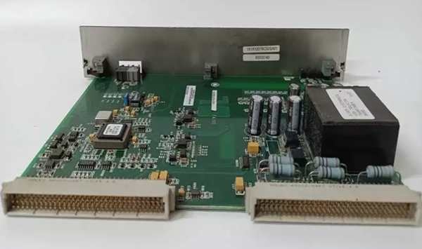
Hardware Architecture & Under-the-Hood Logic
This isn’t a logic processor; it’s a heavy-duty passive power electronics module designed to withstand extreme electrical stress. It lives in a high-vibration, high-EMI environment, acting as the physical gatekeeper for shaft discharge currents. The “G1A” suffix indicates optimized thermal management and resistor selection for harsh industrial use.
- High-Current Terminal Acquisition: Massive cables (up to #4 AWG) land on the heavy-duty terminal blocks. One side connects to the generator shaft grounding brush; the other connects to the plant’s clean safety ground.
- Configurable Resistor Network: Inside the module, a carefully selected bank of high-wattage, non-inductive resistors is wired in series/parallel combinations. This allows you to dial in the exact resistance (1 Ohm to 100 Ohms) needed to limit the discharge current to a safe level (e.g., 5-10 Amps).
- Thermal Dissipation & Protection: The resistors are mounted on massive heatsinks with dedicated airflow channels. Integrated thermostats monitor the resistor temperature. If the duty cycle causes overheating, a thermostat opens, illuminating the “Over-Temp” LED and alerting the operators.
- Deterministic Current Limiting: When a shaft voltage spike occurs, the current attempts to flow to ground. The ERRR module presents a high impedance, choking the current flow to a controlled, non-destructive level, protecting the brush and shaft journal from thermal and electrochemical damage.
Field Service Pitfalls: What Rookies Get Wrong
Selecting the Wrong Resistance Value for the Duty Cycle
A rookie installs a new ERRR module and blindly selects the lowest resistance (1 Ohm) because “lower is better for grounding.” During steady-state operation, the constant shaft voltage pushes 50 Amps through the 1-Ohm resistor, generating massive heat. The resistor glows cherry red and fails open-circuited within hours.
- Field Rule: Consult the generator manufacturer’s shaft voltage study before selecting the resistor value. Use a clamp meter to measure the steady-state shaft current. Select a resistance that limits the current to the brush’s continuous rating (usually 5-10 Amps). Over-limiting is just as dangerous as under-limiting.
Using Undersized Wire for the Grounding Brush Connection
A junior engineer reuses some leftover #10 AWG wire to connect the ERRR module to the generator shaft grounding brush. During a lightning strike, a massive shaft voltage spike dumps 1000 Amps through the suppression path for 10 milliseconds. The #10 AWG wire acts like a fuse, vaporizing instantly and leaving the shaft unprotected during the event.
- Quick Fix: Always use minimum #4 AWG (21 mm²) stranded copper wire for the grounding brush connections. The wire must handle the peak instantaneous current (often > 1000 Amps) without fusing. Crimp on heavy-duty compression lugs and torque them down to 30 lb-in.
Mounting the Module in a Dead-Air Space
A mechanic mounts the ERRR module inside a sealed, unventilated junction box next to the generator. The module’s heatsinks have no access to cooling air. After a few weeks of operation, the internal thermostat trips, opening the suppression circuit and allowing shaft currents to flow unchecked again.
- Field Rule: Always mount the ERRR module in a location with forced-air ventilation or natural convection. Ensure the heatsink fins are not blocked by cables or the cabinet wall. If forced air is unavailable, derate the continuous current capability by 50%.
Commercial Availability & Pricing Note
Please note: The listed price is for reference only and is not binding. Final pricing and terms are subject to negotiation based on current market conditions and availability.


