
Description
Hard-Numbers: Technical Specificiations
- Supply Voltage: 24 VDC (sourced from EPSM module)
- Digital Input Channels: 16 channels (24VDC sinking/sourcing selectable)
- Digital Output Channels: 12 channels (Relay outputs, 250VAC/30VDC rating)
- Analog Input Resolution: 16-bit (0-20mA / 4-20mA selectable)
- Data Update Rate: < 10 ms (end-to-end)
- Isolation Rating: 1500V AC between field I/O and backplane logic
- Operating Temperature: -40°C to +85°C
- Protocol Support: Modbus TCP/IP, Profibus DP, EtherNet/IP, DeviceNet
- Mounting Type: 6U slot, ERBP backplane compatible
- Diagnostic LEDs: Power, Comm Active, Channel Fault (Per Channel)
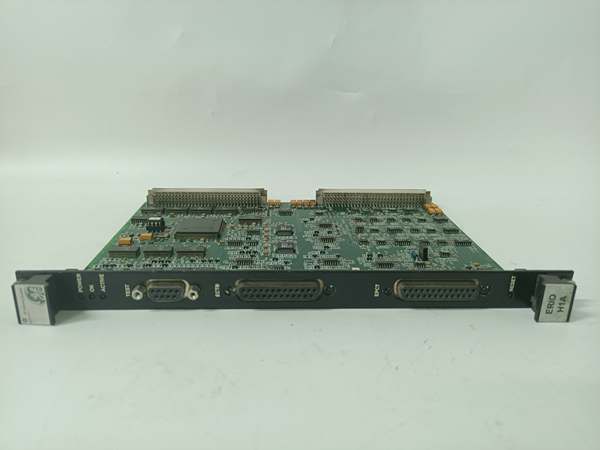
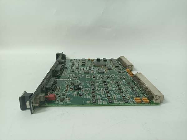
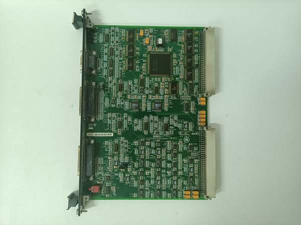
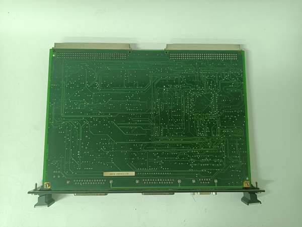
GE IS200ERIOH1A
The Real-World Problem It Solves
You’re troubleshooting a 9FA gas turbine that’s tripping on “Excitation Feedback Loss” because the old discrete I/O wiring is picking up EMI from the 4160V switchgear, corrupting the PT/CT feedback signals to the DSPX controller. You need a hardened module that can aggregate all field signals, scrub the electrical hash, and push clean data to the controller without adding latency. This ERIO board eliminates that nightmare. It consolidates up to 28 field I/O points into a single backplane slot, cutting cabinet wiring volume by 60% and eliminating noise-induced false trips.
Where you’ll typically find it:
- EX2100/EX2100e Exciter Cabinets: Mounted on the ERBP backplane, collecting PT/CT, breaker status, and contact input signals for the DSPX.
- Retrofit Projects: Replacing legacy relay panels and discrete I/O blocks in aging turbine control systems to reduce cabinet footprint and wiring failures.
- Offshore Platform Turbine Skids: Providing isolated I/O for SIS-rated components in Class 1 Div 2 zones with high salt spray exposure.
It turns a tangled, noise-prone I/O wiring system into a deterministic, low-latency signal aggregation hub.
Hardware Architecture & Under-the-Hood Logic
This isn’t a passive terminal block; it’s a smart signal conditioner with multi-protocol communication capability. It lives on the ERBP backplane, acting as the frontline filter between harsh field environments and the sensitive excitation controller. The “H1A” suffix indicates optimized trace routing and enhanced component selection for high-reliability deployments.
- Field Signal Conditioning: Raw 4-20mA analog signals and 24VDC digital inputs are first passed through galvanic isolation and RC filters. This removes common-mode noise, EMI, and transient spikes before the signal ever reaches the internal processor.
- Onboard Signal Scaling & Validation: An integrated ASIC (Application Specific Integrated Circuit) scales the incoming signals to engineering units and runs self-diagnostics on each channel. If a CT input drifts out of range or a digital input is stuck, the ASIC flags the channel fault immediately.
- Backplane Data Packet Assembly: Processed data is packaged into a deterministic packet and transmitted over the ERIB (Exciter Regulator Internal Bus) to the DSPX controller with less than 10ms latency.
- Multi-Protocol Field Interface: Beyond backplane communication, the ERIO supports standard industrial protocols (Modbus TCP/IP, etc.) allowing integration with third-party SCADA or historian systems for trend logging and remote monitoring.
GE IS200ERIOH1A
Field Service Pitfalls: What Rookies Get Wrong
Mismatching Digital Input Sinking/Sourcing Configuration
A rookie lands a 24VDC sourcing sensor output to an ERIO channel configured for sinking input. The channel reads a permanent “High” state regardless of the sensor’s actual status. The turbine trips on “Breaker Failure” because the ERIO reports the generator breaker is closed when it’s actually open.
- Field Rule: Before landing any field device, verify the digital input configuration jumpers on the ERIO’s DIP switch block. Document the jumper settings of the old board before replacement. A mismatched sinking/sourcing config will cause false positives on every digital input channel.
Using Unshielded Twisted Pair for 4-20mA Analog Inputs
A junior engineer uses standard Cat5 Ethernet cable for the 4-20mA PT/CT input runs from the switchgear to the ERIO. The EMI from the adjacent 4160V bus induces ghost currents on the cable, causing the DSPX to see wild fluctuations in generator terminal voltage. The AVR oscillates and trips the turbine.
- Quick Fix: Always use shielded twisted pair (STP) cable for all analog input runs longer than 10 feet. Ground the shield at the ERIO terminal strip end only, using the dedicated chassis ground points on the module’s faceplate. A floating shield is a guaranteed noise antenna.
Skipping the Channel Calibration Routine Post-Installation
A mechanic replaces a failed ERIO and skips the calibration procedure. The onboard ASIC’s analog-to-digital converter has a 1% tolerance variance from the factory spec. The ERIO reports a generator field current of 2800A when the actual current is 2900A. The AVR thinks the excitation is underperforming and overcompensates, causing the generator to overheat.
- Field Rule: After installing any ERIO, perform the channel calibration routine using ToolboxST. Verify the module’s readings against a calibrated multimeter on at least 3 points (0%, 50%, 100% of range). A miscalibrated analog input channel is a guaranteed recipe for AVR instability.
Commercial Availability & Pricing Note
Please note: The listed price is for reference only and is not binding. Final pricing and terms are subject to negotiation based on current market conditions and availability.


