
Description
Hard-Numbers: Technical Specificiations
- 125VDC Input Rating: Up to 40 Amps (monitored & protected)
- 24VDC Input Rating: Up to 20 Amps (monitored & protected)
- Operating Temperature: -20°C to +60°C
- Mounting Location: Exciter Power Backplane Rack (EPBP)
- Diagnostic LEDs: Power Status, Overcurrent Fault, Relay Active
- Response Time: < 10 ms (fault detection to trip signal)
- Isolation Rating: Basic isolation between input rails and logic outputs
- Communication Interface: Backplane (Status reporting to DSPX)
- Onboard Components: Current sensing shunts, Comparators, Triac drivers
The Real-World Problem It Solves
You’re troubleshooting a 9FA gas turbine that just had a “Field Overcurrent” event. The old linear protection relays were too slow to react to a sudden short in the thyristor bridge, allowing a massive current spike to fry the expensive gate drive boards and melt the copper bus bars. You need a board that can sense a current anomaly in microseconds and physically cut the power before the magic smoke escapes.
Where you’ll typically find it:
- EX2100/EX2100e Exciter Cabinets: Mounted in the EPBP rack, monitoring the 125VDC and 24VDC bus bars for overcurrent conditions.
- Heavy-Duty Coal & Gas Plants: Protecting multi-million dollar excitation control electronics from catastrophic short-circuit damage.
- Retrofit Projects: Replacing slow-acting thermal overload relays with fast-acting electronic protection in legacy turbine control rooms.
It turns a slow, clunky protection scheme into a deterministic, sub-10ms hardware trip loop.
Hardware Architecture & Under-the-Hood Logic
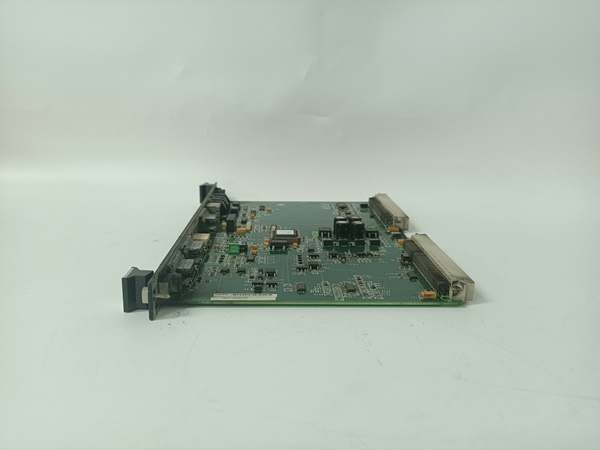
This board doesn’t have a microprocessor; it’s a pure hardware protection circuit designed to fail-safe. It lives on the EPBP backplane, acting as the pit bull guarding your excitation system’s power supply. The “H1A” suffix indicates optimized trace routing and enhanced component selection for faster response times.
- High-Current Sensing & Shunt Measurement: Precision shunts are placed inline with the 125VDC and 24VDC power feeds. The board continuously measures the millivolt drop across these shunts, calculating the instantaneous current draw in real-time.
- Analog Comparator Thresholding: The measured current values are fed into hardwired analog comparators. These chips compare the live current against a factory-set threshold. If the current exceeds the limit, the comparator flips its output state in nanoseconds.
- Hardware Trip Signal Generation: The comparator’s output drives a Triac or heavy-duty relay driver. This instantly sends a hardwired “Trip” signal to the EMIO board and the EDEX firing gate, physically cutting off the gate pulses to the thyristor bridge.
- Backplane Status Reporting: Simultaneously, the board asserts a digital fault bit on the backplane. The DSPX controller reads this bit and logs the “Overcurrent Trip” event on the HMI for the operators to see.
Field Service Pitfalls: What Rookies Get Wrong
Forgetting to Calibrate the Current Sensing Shunts
A rookie replaces a failed ERDC board and skips the calibration procedure. The board’s internal shunt resistance has a slight variance from the factory spec. Two weeks later, the turbine keeps tripping on “False Overcurrent” during normal load ramps because the board thinks 35 Amps is a short circuit.
- Field Rule: After installing a new ERDC, perform the shunt calibration routine outlined in the GE toolset manual (e.g., ToolboxST). Use a calibrated current clamp to verify the board’s reading matches the actual DC bus current within 2%.
Neglecting the 24VDC Sense Leads
A mechanic is cleaning the exciter cabinet and accidentally knocks the small-gauge sense leads off the 24VDC bus bar terminals. He doesn’t notice. A few days later, a legitimate short occurs in the DSPX processor. Because the ERDC lost its sense connection, it can’t detect the spike. The DSPX board is incinerated, and the outage extends by a week.
- Quick Fix: Always tug-test the small-gauge sense leads on the 125VDC and 24VDC bus bars after any cabinet intrusion. Apply a dab of hot glue or a zip-tie to strain-relieve these fragile wires. If the sense leads are open, the protection is blind.
Using Excessive Torque on the Bus Bar Lugs
A junior engineer uses a 1/2-inch drive ratchet to tighten the ERDC’s main power lugs onto the EPBP bus bars. He cranks them down with 50 lb-in of torque. The soft copper lugs cold-flow and crack. During the next peak load, the lug shears off, creating a spectacular arc flash that destroys the entire backplane.
- Field Rule: Use a calibrated torque wrench or screwdriver for all bus bar terminations. The ERDC’s lugs are typically brass or soft copper—stick to the manual’s spec (usually 25-35 lb-in). Over-torquing is a guaranteed recipe for a future arc flash.
Commercial Availability & Pricing Note
Please note: The listed price is for reference only and is not binding. Final pricing and terms are subject to negotiation based on current market conditions and availability.


