

Description
Hard-Numbers: Technical Specificiations
- Input Voltage: 125 VDC (TB1 Positive, TB2 Negative)
- Power Distribution Rails: 5 VDC, 24 VDC, ±15 VDC (sourced from EPSM)
- Communication Bus: ERIB (Exciter Regulator Internal Bus) with <1 ms data latency
- Supported Protocols: Modbus TCP/IP, EtherNet/IP, Modbus RTU
- Module Slots: 8 slots (6U height)
- Operating Temperature: -40°C to +85°C
- Mounting Standard: 35 mm DIN-rail mount or panel-mount compatible
- Physical Dimensions: 320 mm (L) x 240 mm (W) x 100 mm (D)
- Weight: Approx. 3.2 kg (7.05 lbs)
- Protection Features: Slot-level over-current protection, Reverse-polarity protection
GE IS200ERBPG1A
The Real-World Problem It Solves
You’re staring at a legacy power plant control room where the old analog excitation wiring is a bird’s nest of spaghetti, causing erratic generator voltage and frequent trips. Your modern EX2100 digital modules need a rigid physical chassis to mount into, and they need to talk to the plant’s DCS without buying a separate, expensive gateway box.
Where you’ll typically find it:
- Combined-Cycle Power Plants: Acting as the central hub connecting DSPX controllers, EPSM power supplies, and ERIO I/O boards within the exciter rack.
- Hydroelectric Stations: Enabling remote monitoring of excitation parameters via EtherNet/IP for turbines in remote, harsh environments.
- Industrial Captive Power Plants: Bridging the gap between the EX2100 excitation stack and existing PLC/SCADA infrastructures using Modbus protocols.
It turns a messy pile of loose wires and disparate control modules into a deterministic, standardized, and externally integrated control backbone.
Hardware Architecture & Under-the-Hood Logic
This isn’t an active processing board with a CPU; it’s the industrial-grade skeleton of your excitation rack. It lives in the control cabinet, acting as the rigid mechanical chassis and the high-speed electrical nervous system for your digital modules. The “G1A” suffix indicates optimized trace routing and robust component selection for heavy industrial use.
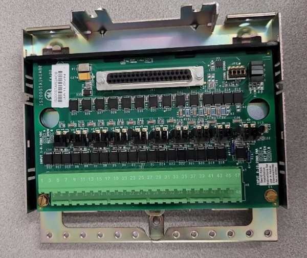
- Mechanical Skeleton & Slot Allocation: The ERBP provides 8 ruggedized 6U slots milled to exact tolerances. You slide in your EPSM power supplies, DSPX controllers, and ERIO I/O packs. This ensures perfect alignment of the rear-mounted connectors, preventing bent pins or intermittent contact.
- High-Speed ERIB Communication Bus: An integrated Exciter Regulator Internal Bus (ERIB) runs the length of the backplane. It transfers data between slots with less than 1 millisecond of latency, ensuring the DSPX processor gets real-time feedback from the power bridge and I/O boards without lag.
- Integrated Power Rail Distribution: Instead of running individual power wires to every module, the ERBP features integrated copper power rails. It takes the bulk 125VDC input and distributes conditioned 5 VDC, 24 VDC, and ±15 VDC across all 8 slots via the backplane connectors.
- Protocol Gateway & External Comms: Unlike a dumb backplane, this unit integrates a protocol gateway. It translates the internal EX2100 proprietary bus language into standard industrial protocols (Modbus TCP/IP, EtherNet/IP). This allows the plant’s central DCS or SCADA system to read generator field current and voltage directly without needing external hardware.
GE IS200ERBPG1A
Field Service Pitfalls: What Rookies Get Wrong
Bending Module Pins Due to Misaligned Slot Entry
A rookie is sliding a heavy DSPX processor into Slot 3 of the ERBP. He pushes it in crooked, and the rear-mounted gold pins crash into the side of the backplane connector. He forces it in, bending three pins and shorting the 5VDC rail to ground. The EPSM immediately shuts down due to an over-current fault, killing the entire exciter rack.
- Field Rule: Never force a module into the slot. If it doesn’t slide in smoothly with minimal hand pressure, pull it out and inspect the rear pins. Align the module perfectly vertically before applying forward pressure. A bent pin on a backplane connector is often a death sentence for the entire board.
Using a Screwdriver Instead of a Torque Wrench on TB1/TB2
A mechanic is landing the main 125VDC station battery leads onto the ERBP’s power connectors (TB1 and TB2). He grabs a standard flathead screwdriver and cranks the screws down as hard as he can. He over-torques the brass terminals, causing the metal to cold-flow and crack. During a peak load swing, the TB1 terminal shears off, creating a violent arc flash that welds the blade of the disconnect switch shut.
- Quick Fix: Always use a calibrated torque screwdriver or wrench for the 125VDC power terminals (TB1/TB2). Refer to the GE manual for the exact inch-pound setting (usually around 15-20 lb-in). Over-torquing copper and brass terminals is a guaranteed way to cause a future catastrophic failure.
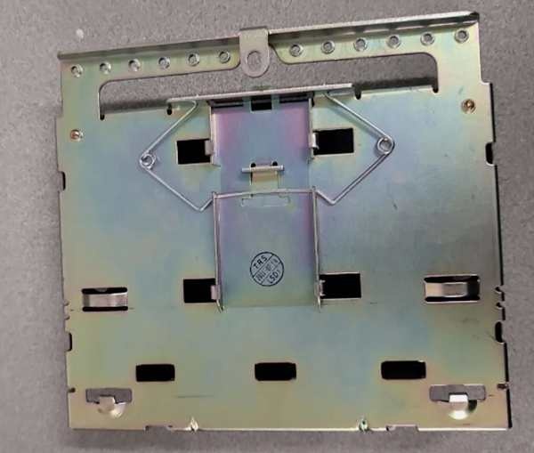
Skipping the DIN-Rail Retaining Clip on Vibrating Skids
An engineer mounts the ERBP onto a standard 35mm DIN rail inside an offshore platform turbine enclosure. He slides it on but forgets to flip the plastic retaining clip at the bottom of the rail channel. Three months later, the constant low-frequency vibration from the gas turbine causes the backplane to slowly walk itself off the rail. The unit loses power and communication, triggering a massive unplanned shutdown.
- Field Rule: Always engage the DIN-rail retaining clip. Give the bottom of the backplane a firm upward tug after mounting to ensure it is locked in place. In high-vibration environments, apply a dab of blue Loctite to the clip pivot point for extra security.
Commercial Availability & Pricing Note
Please note: The listed price is for reference only and is not binding. Final pricing and terms are subject to negotiation based on current market conditions and availability.


