
Description
Hard-Numbers: Technical Specificiations
- Input Voltage: 125 VDC (sourced from EPDM power module)
- Gate Output Voltage: Up to ±20V (configurable via jumpers)
- Gate Output Current: Peak > 3.0 Amps
- Operating Temperature: -20°C to +60°C
- Isolation Rating: Optically isolated gate drive outputs
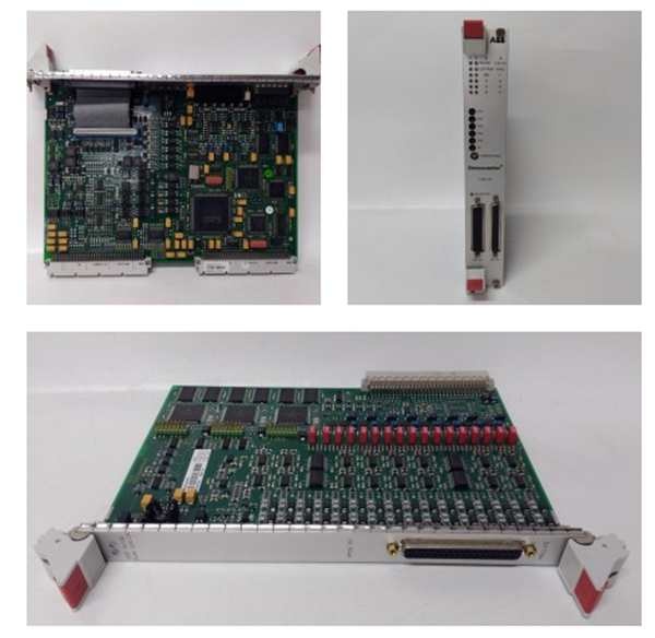
- Mounting Location: Exciter Power Backplane Rack (EPBP)
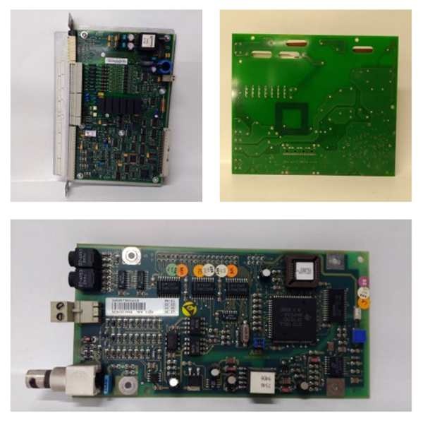
- Diagnostic LEDs: Power, Active, Output Fire, Line Filter, Fault
- Connectors: High-density terminal blocks & multi-pin bridge interface
GE IS200EPCTG1A
The Real-World Problem It Solves
You’re troubleshooting a 9FA gas turbine that keeps hunting on VARs because the generator field current is oscillating. The old power conversion board is struggling to push enough current through the gate-cathode junction of the aging thyristors, causing inconsistent firing angles and poor voltage regulation. You need a board that can deliver hammer-blow gate pulses to keep the SCRs saturated. This EPCT board eliminates that headache. It integrates a beefy DC/DC converter and high-speed drive transistors to ensure your thyristor bridge fires crisply and maintains rock-solid generator terminal voltage.
Where you’ll typically find it:
- EX2100 Exciter Power Cabinets: Directly mounted in the EPBP rack, interfacing with the ESEL selector and the thyristor bridge.
- Large Synchronous Generators: Managing field current regulation in 500MW+ combined-cycle and nuclear units.
- Retrofit Projects: Upgrading legacy analog excitation power stages with modern, digitally controlled gate drivers.
It turns a sluggish, voltage-hunting excitation system into a deterministic, high-energy firing loop.
Hardware Architecture & Under-the-Hood Logic
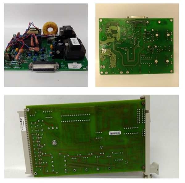
This isn’t just a passive terminal block; it’s an active power amplifier designed to survive the brutal electrical environment right next to a multi-megawatt thyristor bridge. It lives on the EX2100 backplane, acting as the muscle between the ESEL board’s logic and the violence of the power bridge. The “G1A” suffix indicates specific trace routing and component selections for enhanced thermal performance.
- Gate Pulse Reception & Buffering: Firing commands arrive from the ESEL (Exciter Selector) board via the backplane. The EPCT buffers these millisecond-precision logic signals to ensure clean edges before amplification.
- High-Current DC/DC Conversion: An onboard converter takes the 125VDC input and generates the high-current gate drive voltage. This is what gives the pulses the “punch” needed to overcome SCR gate capacitance and ensure simultaneous turn-on across all phases.
- Bridge Output Stage: The conditioned, high-current pulses are routed through heavy-duty terminal blocks and multi-pin connectors to the thyristor gates. The onboard LEDs give you an instant visual confirmation of which pulse is firing and if the line filter is healthy.
- Fault Latching & Protection: Integrated comparators constantly monitor the output stage for signs of saturation or open circuits. If a fault is detected (like a shorted gate or a blown line filter), the board instantly latches a hardware fault and kills the gate drive outputs to protect the generator rotor.
GE IS200EPCTG1A
Field Service Pitfalls: What Rookies Get Wrong
Using Undersized Wire for the 125VDC Input Lugs
A junior engineer reuses some leftover #16 AWG wire for the 125VDC input from the EPDM module to save money. During a peak load ramp, the EPCT draws heavy current, cooking the wire to 100°C. The insulation melts, creating a short circuit that blows the plant’s entire 125VDC distribution breaker and blacks out the control system.
- Field Rule: Use minimum #12 AWG (4mm²) stranded copper wire for the 125VDC input. Crimp on heavy-duty compression lugs and torque them down to 15 lb-in. Slap some anti-oxidizing paste on the lugs to fight off corrosion-induced resistance creep.
Ignoring the 5 Onboard Jumpers (J1-J5) on Replacement
A rookie swaps a dead EPCT and ignores the jumpers, assuming the factory defaults are universal. The turbine powers up, but the gate pulses are out of phase with the AC sine wave. Severe harmonic distortion appears in the generator terminal voltage, leading to excessive rotor heating within hours.
- Quick Fix: Photograph the J1 through J5 jumper settings on the old board before removal. These jumpers control pulse width, polarity, and voltage levels. Replicate them exactly. If you’re upgrading from a previous revision, consult the site-specific manual to verify the jumper map matches your SCR module specifications.
Letting the Gate Drive Cables Rest on Sharp Edges
A mechanic is routing the thick gate drive cables from the EPCT to the thyristor bridge. He carelessly lays them over the sharp, untreated edge of the steel cabinet frame. Over time, the vibration causes the cable jackets to abrade. Eventually, a live 125VDC wire touches the grounded frame, instantly destroying the EPCT’s output stage.
- Field Rule: Always use rubber grommets or high-temperature edge protectors wherever cables pass through metal openings. Secure the cables with nylon tie-wraps, keeping them away from sharp edges and high-heat sources. A five-cent grommet can save you a $10,000 board.
Commercial Availability & Pricing Note
Please note: The listed price is for reference only and is not binding. Final pricing and terms are subject to negotiation based on current market conditions and availability.


