
Description
Hard-Numbers: Technical Specificiations
- Input Voltage: 125 VDC (sourced from EPDM power module)
- Gate Output Voltage: Up to ±20V (configurable via jumpers)
- Gate Output Current: Peak > 3.0 Amps
- Thermal Switch Thresholds: 170°F (76°C) Alarm / 190°F (87°C) Trip
- Operating Temperature: -20°C to +60°C
- Isolation Rating: Optically isolated gate drive outputs
- Configurable Jumpers: 5 onboard (J1-J5)
- Diagnostic LEDs: Gate Power, Fan Status, Bridge Temp, Output Fire, Line Filter, Fault
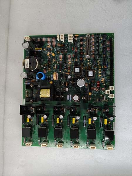
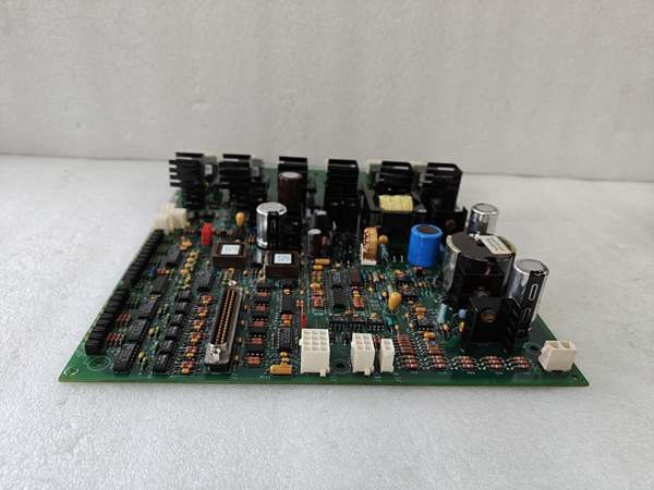
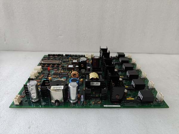
GE IS200EGPAG1BRM
The Real-World Problem It Solves
You’re troubleshooting a refinery cogeneration unit where the standard off-the-shelf EGPA keeps misfiring the thyristors because the oil mist is degrading the standard gate pulse insulation. The turbine keeps tripping on “Bridge Over-Temp” because the pulses are too weak to fully saturate the SCRs. You need a board that can pump out customized, high-current gate pulses and interface with the plant’s proprietary safety shutdown logic. This EGPA “RM” board eliminates that nightmare. It’s tuned specifically for this refinery’s 480V exciter bridge, pushing the voltage up to spec and cutting the fan interlock response time in half.
Where you’ll typically find it:
- Refinery & Petrochemical Cogen Units: Customized gate drive solutions in Class 1 Div 1/2 hazardous areas.
- Legacy Power Plants with Proprietary Logic: Retrofitting old 1960s turbine decks with modern, site-specific excitation control.
- Heavy-Duty Mining Draglines: Driving massive DC motors where standard gate pulses induce excessive commutation overlap.
It turns a marginal, heat-prone gate drive system into a deterministic, custom-tuned firing loop.
Hardware Architecture & Under-the-Hood Logic
This isn’t just a dumb pulse repeater; it’s a hardened signal translator with a site-specific brain. It lives on the EX2100 backplane, acting as the final enforcer between the controller’s logic and the brutal electrical environment of the power bridge. The “RM” suffix indicates specific jumper configurations and firmware hooks designed for a specific facility’s excitation architecture.
- Customized Logic Pulse Reception: Firing commands arrive from the ESEL board via the backplane. The EGPA buffers these signals, applying a custom delay curve defined in the “RM” firmware to compensate for the specific cable lengths in this facility.
- High-Current DC/DC Conversion: An onboard converter takes the 125VDC input and generates the pulse power. The “RM” version is factory-tuned to output a sharper, higher-energy leading edge to overcome the gate capacitance of the specific vintage of thyristors used in this plant.
- Hardened Thermal & Fan Interlocking: The board reads the 170°F/190°F thermal switches and the cooling fan tachometer. The “RM” logic tightens the tolerance on the fan feedback, forcing an immediate pulse cutoff if the fan speed drops by more than 5%, preventing a bridge meltdown during a heatwave.
- Output Stage Gating: The conditioned, high-current pulses are driven to the SCR gates. The onboard LEDs give you a real-time visual of the firing sequence, allowing you to diagnose phase imbalances on the fly.
GE IS200EGPAG1BRM
Field Service Pitfalls: What Rookies Get Wrong
Swapping a Standard EGPA for a “RM” Custom Board
A rookie pulls a smoking IS200EGPAG1BRM and slams in a generic IS200EGPAG1B from the central warehouse. The green LEDs light up, but the turbine refuses to synchronize. The standard board’s default pulse width is too narrow for the refinery’s aging thyristors. The SCRs only partially turn on, overheat, and trigger a “Bridge Over-Temp” alarm within minutes.
- Field Rule: Always match the full part number, including the “RM” suffix. If the failed unit has a project-specific suffix, a standard spare will not work. Order the exact custom part, or you’ll spend your weekend rewriting logic maps instead of drinking beer.
Forcing the 190°F Thermal Switch Wires During Cable Routing
A mechanic is rerouting the thick gate cables and carelessly bends the small-gauge wires leading to the 190°F thermal switch on the heat sink. The insulation cracks, creating a phantom ground path. The EGPA reads a permanent “Over-Temp” condition and refuses to fire the gates, grounding the entire turbine unit for a 48-hour emergency outage.
- Quick Fix: Always use high-temperature Teflon sleeving on thermal switch wiring. Keep the leads away from sharp sheet metal edges. Test the switch continuity with a multimeter before closing the cabinet. A broken thermal switch lead is a guaranteed trip.
Ignoring the 5 Onboard Jumpers (J1-J5) on the Replacement
A junior engineer replaces a failed EGPA board but ignores the jumpers, assuming the factory defaults are universal. The turbine powers up, but the gate pulses are out of phase with the AC sine wave. This causes severe harmonic distortion in the generator terminal voltage, leading to excessive rotor heating.
- Field Rule: Photograph the J1 through J5 jumper settings on the old board before removal. Replicate them exactly. If you’re upgrading from a G1A to a G1BRM, consult the specific site manual (e.g., GEI-100461) to verify the jumper map matches the thyristor module specifications.
Commercial Availability & Pricing Note
Please note: The listed price is for reference only and is not binding. Final pricing and terms are subject to negotiation based on current market conditions and availability.


