
Description
Hard-Numbers: Technical Specifications
- Input Voltage: 125 VDC (sourced from EPDM power module)
- Gate Output Voltage: Up to ±20V (configurable via jumpers)
- Gate Output Current: Peak > 3.0 Amps
- Thermal Switch Thresholds: 170°F (76°C) Alarm / 190°F (87°C) Trip
- Operating Temperature: -20°C to +60°C
- Isolation Rating: Optically isolated gate drive outputs
- Configurable Jumpers: 5 onboard (J1-J5)
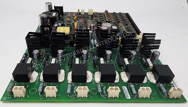
- Diagnostic LEDs: Gate Power, Fan Status, Bridge Temp, Output Fire, Line Filter, Fault
The Real-World Problem It Solves
You’re staring at a 9FA gas turbine that keeps tripping on “Field Overcurrent” during hot summer days. The old firing pulses from the controller are too weak to fully saturate the thyristors (SCRs), causing them to heat up and eventually short. You need a board that can take those weak logic signals and turn them into high-current hammer blows to drive the gates. This EGPA board eliminates that headache. It boosts the pulses to ±20V and monitors the bridge temperature like a hawk, preventing a $500k rotor rewind.
Where you’ll typically find it:
- EX2100 Exciter Power Cabinets: Driving the gates of large thyristor bridges in 500MW+ generators.
- Industrial DC Drive Systems: Providing high-current gate pulses for large rectifiers in aluminum smelting.
- Retrofit Projects: Replacing aging analog firing cards in legacy turbine control systems.
It turns a marginal, heat-prone gate drive system into a deterministic, thermally-protected firing loop.
GE IS200EGPAG1B
Hardware Architecture & Under-the-Hood Logic
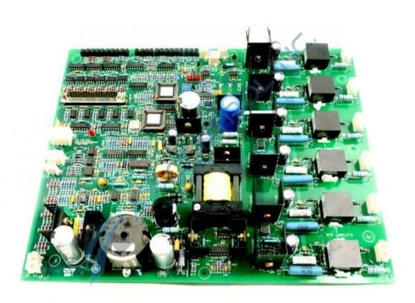
This isn’t a passive splitter; it’s an active pulse amplifier with built-in safety interlocks. It sits on the EX2100 backplane, acting as the final muscle between the controller’s logic and the brute force of the power bridge. The “G1B” suffix indicates specific firmware and jumper optimizations for enhanced thermal management.
- Logic Pulse Reception: Low-voltage firing commands arrive from the ESEL board via the backplane. The EGPA buffers these signals to ensure clean edges before amplification.
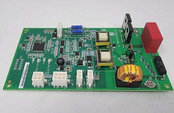
- High-Current DC/DC Conversion: An onboard converter takes the 125VDC input and generates the high-current gate drive voltage. This is what gives the pulses the “punch” needed to overcome SCR gate capacitance.
- Thermal & Fan Feedback Processing: The board directly monitors dual 170°F/190°F thermal switches on the bridge heat sink. It also checks the tachometer feedback from the cooling fan. If the temp hits 190°F or the fan stops, the EGPA instantly kills the gate outputs.
- Output Stage Firing: The conditioned, high-current pulses are sent to the SCR gates through heavy-duty wiring. The onboard LEDs give you instant visual confirmation of which pulse is firing.
Field Service Pitfalls: What Rookies Get Wrong
Ignoring the 5 Onboard Jumpers (J1-J5) During Replacement
A rookie swaps a dead EGPA and doesn’t touch the jumpers. The turbine powers up, but the gate pulses are too narrow for the specific vintage of SCRs in the bridge. The thyristors only partially turn on, heat up like a toaster, and explode during a load ramp.
- Field Rule: Photograph the J1 through J5 jumper settings on the old board before removal. These jumpers control pulse width and voltage levels. Replicate them exactly. If you’re unsure, consult the GEI-100461 manual for your specific SCR part number.
Letting the 190°F Thermal Switch Wires Chafe
A mechanic is rerouting cables in the exciter cabinet and doesn’t secure the thermal switch leads from the bridge. The wires rub against the sharp edge of the heat sink, shorting out. The EGPA thinks the bridge is cool and keeps firing at full tilt, even though the heat sink is glowing red.
- Quick Fix: Always use high-temperature Teflon sleeving on all thermal switch wiring. Secure the wires away from sharp edges with nylon tie-wraps. Test the switch continuity with a multimeter before closing the cabinet.
Using Undersized Wire for Gate Leads
A junior engineer uses #18 AWG wire for the gate leads because it’s easier to route. The high-current pulses cause the wire to act as a resistor, dropping the voltage before it reaches the SCR gate. The thyristors never fully saturate, leading to excessive heat generation and premature failure.
- Field Rule: Use minimum #14 AWG (2.08 mm²) stranded copper wire for all gate drive connections. Keep the leads as short as physically possible. Torque the lugs to 10 lb-in and apply anti-oxidizing paste to prevent resistance buildup.
Commercial Availability & Pricing Note
Please note: The listed price is for reference only and is not binding. Final pricing and terms are subject to negotiation based on current market conditions and availability.


