
Description
Hard-Numbers: Technical Specifications
- DC Input Voltage: 125 VDC (±10%, typically station battery supply)
- AC Input Options: 2x independent 115/220 VAC 50/60Hz supplies
- Downstream Output Rating: 125VDC to DSPX/EAUX/EBRG boards, 24VDC to I/O modules
- Operating Temperature: -20°C to +70°C
- Isolation Rating: 1500V input-to-output, 1000V output-to-chassis
- Communication Interface: High-Speed Serial Link (HSSL) to main processor
- Configurable Switches: 11 total (5 bridge control + 6 function switches)
- MTBF: ≥ 450,000 hours
- Hot-Swap Capable: Yes, zero downtime replacement
The Real-World Problem It Solves
You’re troubleshooting a 9FA gas turbine that keeps tripping on “Exciter Power Failure” during grid transients because the old single-source power supply can’t handle the voltage sags from the station battery bank. You need a hardened power hub that accepts redundant 125VDC and AC feeds, routes power to 20+ downstream modules without overheating, and communicates system health to the HMI. This EDIS board eliminates that headache. It consolidates all power distribution into a single rack-mount unit with built-in redundancy and diagnostic alerts, preventing unplanned outages during the worst grid flickers.
Where you’ll typically find it:
- EX2100/EX2100e Exciter Cabinets: Distributing power to DSPX controllers, EBRG bridge boards, EAUX aux power modules, and all field I/O packs
- Heavy-Duty Fossil & Nuclear Power Plants: Serving as the primary power distribution hub for multi-turbine excitation systems
- Offshore Platform Turbine Skids: Providing isolated, redundant power to SIS-rated components in Class 1 Div 2 zones
It turns a brittle, single-point-of-failure power distribution network into a resilient, monitored energy backbone for your excitation control system.
Hardware Architecture & Under-the-Hood Logic
This isn’t a passive terminal block; it’s an active power conditioning and routing hub designed to survive the harsh electrical environment of a power plant control room. It sits on the EX2100e backplane, acting as the gatekeeper between the plant’s power grid and the sensitive control electronics.
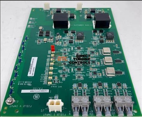
- Multi-Source Input Stage: The board accepts up to three independent power feeds: a primary 125VDC station battery, and two separate 115/220VAC 50/60Hz supplies. An integrated DACA rectifier card converts the AC inputs to DC for seamless redundancy switching.
- Automatic Redundancy Switching: Built-in comparators continuously monitor the input voltages. If the primary 125VDC battery sags below 112VDC, the board instantly switches to the highest-quality available power source, with less than 3ms output sag.
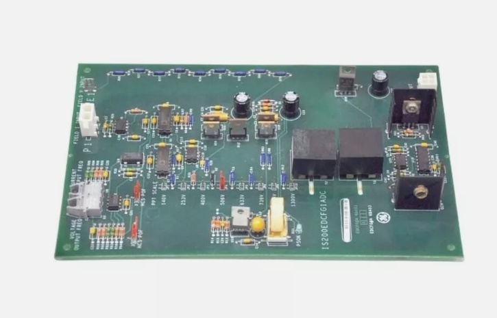
- Configurable Load Routing: Eleven onboard DIP switches (including five dedicated bridge switches) allow you to partition power distribution across Bridge 1 through Bridge 5, and allocate power to auxiliary functions like Ethernet switches and VersaMax I/O modules.
- Health Telemetry & Diagnostics: The board communicates with the main DSPX processor via HSSL, reporting input source health, output load current, and internal temperature to the HMI for predictive maintenance and fault localization.
Field Service Pitfalls: What Rookies Get Wrong
Forgetting to Configure the Bridge Switch DIP Settings
A rookie installs a new EDIS board to replace a failed unit, but forgets to set the five bridge DIP switches to match the plant’s multi-bridge configuration. The turbine powers up, but the Bridge 3 thyristor interface board doesn’t receive power, causing the unit to trip on “Bridge 3 Power Loss” during synchronization.
- Field Rule: Photograph the DIP switch settings of the failed board before removal, then replicate those exact positions on the replacement. Bridge switches control power routing to specific thyristor banks; incorrect settings will starve critical downstream modules.
Using Undersized Wire for 125VDC Battery Input
To save space in a cramped power cabinet, a junior engineer uses #16 AWG wire for the 125VDC 40A station battery input. The high current causes the wire to heat up to 90°C, melting the insulation and creating a short circuit that blows the plant’s 125VDC distribution breaker, taking down the entire control system.
- Quick Fix: Use minimum #12 AWG (4mm²) stranded copper wire for the 125VDC input, crimped with compression lugs and torqued to 15 lb-in. Apply anti-oxidizing paste to all lug connections to prevent corrosion-induced resistance buildup.
Ignoring Input Phase Rotation on AC Feeds
A tech wires two 208VAC 3-phase supplies to the EDIS board but forgets to check phase rotation. The unbalanced load on the neutral conductor causes the internal DACA rectifier to overheat, leading to a catastrophic failure six months later during a storm-induced power fluctuation.
- Field Rule: Always test phase rotation with a phase sequence tester before energizing AC inputs. Match L1-L2-L3 rotation to the plant standard, and torque all AC input lugs to 15 lb-in to prevent loose connections that cause arcing and hot spots.
Commercial Availability & Pricing Note
Please note: The listed price is for reference only and is not binding. Final pricing and terms are subject to negotiation based on current market conditions and availability.


