
Description
Hard-Numbers: Technical Specifications
- Logic Input Voltage: 24 VDC (±10%)
- Exciter Power Input: 125 VDC (EDIS supply, ±10%)
- Operating Temperature: -30°C to +65°C
- Power Draw: Approx. 18 Watts
- Communication Interface: Fiber-Optic (High-Speed Serial) & 9-pin D-sub
- Isolation Rating: 2500 VAC Input-to-Output
- MTBF: ≥ 350,000 hours
- Form Factor: Single-slot 6U CompactPCI
- Diagnostic Indicators: Run, Fault, and Watchdog LEDs
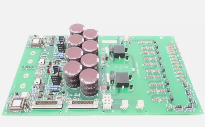
GE IS200EDEXG1B
The Real-World Problem It Solves
You’re sweating bullets in a 9FA gas turbine exciter cabinet. The old copper-wired gate drive is picking up harmonic distortion from the nearby 4160V bus, causing the thyristors to misfire and the generator voltage to hunt. You need a board that can take the firing angles from the DSPX, completely isolate them from the brutal 125VDC exciter power, and deliver rock-solid gate pulses. This EDEX board solves that nightmare. It acts as the hardened bouncer between your delicate 24VDC control logic and the violent electrical world of the power bridge, preventing a false trip during a grid transient.
Where you’ll typically find it:
- EX2100 / Innovation Series Exciter Cabinets: Bridging the DRLY/DSPX controller and the thyristor (SCR) power bridge.
- Heavy-Duty Steam Turbine Generators: Managing gate firing sequences for massive brushless exciters during load rejections.
- Retrofit Projects: Replacing obsolete analog firing interface cards in legacy turbine-generator sets to improve MTBF.
It turns a noisy, high-risk gate drive system into a deterministic, optically isolated control loop.
Hardware Architecture & Under-the-Hood Logic
This board doesn’t just pass data; it’s a hardened signal translator and power amplifier. It lives on the Mark VIe backplane, acting as the muscle between the logic world of the controller and the violent electrical environment of the power bridge. The “BBB” suffix indicates specific firmware baselines and enhanced thermal component selection.
- Fiber-Optic Logic Reception: Firing commands arrive via a ruggedized fiber-optic cable from the DRLY or DSPX board. This completely eliminates ground loops and EMI susceptibility, ensuring the firing angle is received exactly as intended.
- Galvanic Isolation & Level Shifting: The 24VDC logic signals are immediately isolated from the 125VDC exciter power plane using high-speed optocouplers. This prevents a bridge-side short circuit from frying the delicate Mark VIe controller.
- High-Current Gate Amplification: Raw logic pulses are fed into high-speed power transistors (IGBTs or MOSFETs). These push the voltage up to the exact +15V / -5V levels required to force the thyristors into saturation, ensuring crisp, simultaneous firing across all phases.
- Hardware Self-Diagnostics: Integrated comparators constantly monitor the gate-cathode voltage for signs of transformer saturation or open circuits. If a fault is detected, the board instantly latches a hardware fault and kills the gate drive outputs to protect the multi-million-dollar generator rotor.
GE IS200EDEXG1B
Field Service Pitfalls: What Rookies Get Wrong
Crushing the Fiber-Optic Connector with Bare Hands
A rookie is connecting the fiber patch cable from the DRLY to the EDEX board. He grips the ST-connector body and twists it hard to “make sure it’s in.” He cracks the internal ceramic ferrule. Two weeks later, the turbine trips on “Exciter Logic Loss” because the optical signal is attenuated below the receiver’s threshold.
- Field Rule: Hold the connector by the strain-relief boot, not the body. Insert with gentle, steady pressure until you feel the click of the retention sleeve. Never torque an optical connector; treat it like a fuse.
Mixing Up 24VDC and 125VDC Power Lugs
A tech is doing a routine PM and accidentally lands the 24VDC supply wire onto the 125VDC EDIS input lug. He flips the breaker. The 125VDC instantly incinerates the onboard 24VDC regulator and blows the power MOSFETs. The board is a total loss, and the turbine outage extends by three days.
- Quick Fix: Always verify the wire labels and lug markings with a multimeter before energizing. The 24VDC and 125VDC inputs are often located right next to each other. Mark the 125VDC lugs with a bright red paint pen or a zip-tie flag to prevent accidental cross-wiring.
Ignoring the Thermal Paste on the Power Devices
A mechanic cleans the EDEX board’s heatsink fins with compressed air during an outage. He inadvertently wipes off some of the thermal interface material between the power MOSFETs and the heatsink. Six months later, during a full-load rejection test, the localized hot spot causes thermal runaway, and the board fails on “Gate Drive Overcurrent.”
- Field Rule: Never disturb the thermal interface material between the power semiconductors and the heatsink. If you must remove a board for deep cleaning, reapply a high-quality thermal grease (like Arctic Silver) before reinstalling. A dry thermal junction is a guaranteed premature failure.
Commercial Availability & Pricing Note
Please note: The listed price is for reference only and is not binding. Final pricing and terms are subject to negotiation based on current market conditions and availability.


