
Description
Hard-Numbers: Technical Specifications
- Input Voltage: 24 VDC (±10%)
- Power Draw: Approx. 15 Watts
- Pulse Output Voltage: +15V / -5V (adjustable)
- Pulse Output Current: Peak 3.0 Amps
- Synchronization Input: 3-Phase PT Input (100V – 130V RMS)
- Communication Interface: Fiber-Optic (proprietary protocol)
- Operating Temperature: -30°C to +65°C
- Isolation Rating: 2500 VAC Input-to-Output
- Protection Features: Gate-cathode short detection, Pulse transformer saturation monitor
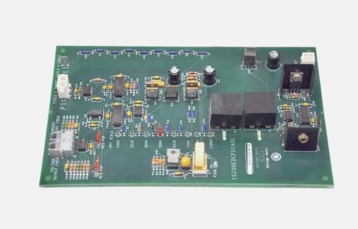
IS200EDCFG1BAA
The Real-World Problem It Solves
You’re staring at an EX2100 exciter cabinet where the old firing cables are picking up crosstalk from the nearby 4160V bus. The thyristors are misfiring, making the generator voltage hunt and putting stress on the rotor windings. You need a board that can take the millisecond-precision firing angles from the DSPX, amplify them into hard-hitting gate pulses, and shoot them down the line without a hint of jitter. This EDC board fixes that mess. It provides complete optical isolation and robust pulse amplification, ensuring your thyristor bridge fires exactly when told.
Where you’ll typically find it:
- EX2100 Exciter Cabinets: Mounted directly behind the thyristor power bridge, driving gate pulses for large-scale synchronous generators.
- High-Voltage DC Drive Systems: Managing commutation logic for large industrial rectifiers.
- Turbine-Generator Retrofits: Replacing aging analog firing cards to improve voltage regulation stability.
It turns a noisy, high-energy firing system into a deterministic, optically isolated control loop.
Hardware Architecture & Under-the-Hood Logic
This isn’t just a dumb power amplifier; it’s a hardened signal translator built to survive the brutal electrical environment right next to a multi-megawatt thyristor bridge. It sits on the EX2100 backplane, acting as the muscle between the delicate DSPX processor and the violent world of power electronics. The “BAA” suffix indicates optimized thermal planes and enhanced component selection.
- Optical Signal Decoding: Firing commands arrive via ruggedized fiber-optic cables from the HSLA/DSPX boards. This completely eliminates ground loops and EMI susceptibility that plague copper-wired systems.
- Phase Synchronization & PLL: The board taps directly into the generator PT signals. An onboard Phase-Locked Loop (PLL) circuit locks onto the 60Hz fundamental, ensuring the firing pulses are perfectly synchronized with the AC sine wave, regardless of grid frequency fluctuations.
- High-Current Pulse Amplification: Raw logic-level pulses are fed into high-speed Darlington transistors. These push the voltage up to +15V and drive several amps of current into the gate-cathode circuit of the thyristors, guaranteeing a crisp, simultaneous turn-on across all phases.
- Self-Diagnostics & Snubber Logic: Integrated comparators constantly monitor the gate-cathode voltage. If a pulse transformer saturates or a thyristor fails to latch, the board immediately latches a hardware fault and cuts power to prevent a catastrophic shoot-through event.
IS200EDCFG1BAA
Field Service Pitfalls: What Rookies Get Wrong
Crushing the Fiber-Optic Transceiver with Excessive Force
A rookie is connecting the fiber patch cable from the DSPX to the EDC board. He presses the ST-connector into the receptacle with his thumb, using way too much force. The internal lens cracks, and the optical alignment shifts. Two days later, the turbine trips on “Sync Loss” because the firing pulses are arriving with a 10-degree phase error.
- Field Rule: Treat fiber connectors like fine china. Insert the ST or SMA connector with gentle, steady pressure until you feel the click of the retention sleeve. Never force the connector. If you feel resistance, pull back, inspect the ferrule for dirt, and try again.
Ignoring the Pulse Transformer Snubber Resistor Network
A tech is troubleshooting a “Gate Drive Overcurrent” alarm. He notices a slightly discolored resistor in the snubber network on the EDC board and bypasses it with a piece of wire to “see if it works.” The lack of damping causes the gate-cathode voltage to ring violently, inducing a parasitic turn-on in the adjacent thyristor, which promptly explodes.
- Quick Fix: Never bypass or alter passive components on the EDC board. If a snubber resistor shows signs of thermal stress, replace the entire EDC board. The resistor values are precisely calculated to dampen LC oscillations specific to your thyristor bridge’s parasitic capacitance.
Mounting the Board Too Close to the Power Bridge Heat Sink
During a cabinet layout redesign, a junior engineer mounts the EDC board only 2 inches away from the 1000A thyristor heat sink to save space. During a full-load rejection test, the radiant heat soaks the EDC’s PLL circuit, causing a thermal drift in the synchronization logic. The generator voltage starts oscillating wildly.
- Field Rule: Maintain a minimum 6-inch (150mm) air gap between the EDC board and any high-wattage heat-generating components (thyristors, diode bridges). If space is tight, install a small 24VDC baffle fan to force cool air across the EDC’s PLL components. Heat is the enemy of precision timing.
Commercial Availability & Pricing Note
Please note: The listed price is for reference only and is not binding. Final pricing and terms are subject to negotiation based on current market conditions and availability.


