
Description
System Architecture & Operational Principle
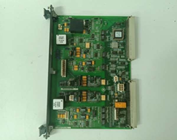
The is a passive terminal board mounted in the EX2100 Exciter Cabinet, specifically designated for Redundant (TMR) architectures. It serves as the field-facing I/O hub for critical contact signals, bridging the gap between the turbine deck and the VME controllers.
Physically, it mounts to the cabinet frame. Upstream, it connects to the EMIO (Exciter Master I/O) boards in the M1, M2, and C cores via three 25-pin D-Sub connectors (J405, J408, J415). Downstream, it handles the heavy lifting: it terminates six auxiliary contact inputs (powered/wetted by an isolated 70V DC supply from the EPSM) and hosts two heavy-duty Trip Relays (K1, K2) typically used to drive customer lockout circuits or interface with the turbine’s TRLY (Trip Relay) boards. It also provides four General Purpose Form-C relays (K1GP-K4GP) controlled by the EMIO for auxiliary sequencing (e.g., field flashing, cubicle cooling). In a TMR setup, this board is replicated across the M1, M2, and C cores, ensuring that a wiring fault on the ‘M1’ physical terminal doesn’t disable the ‘M2’ or ‘C’ protection paths.
IS200ECTBG1A
Core Technical Specifications
- Operation Mode: Redundant Only (G1 Suffix denotes Redundant; G2 is Simplex)
- Trip Outputs: 2x Form-C Relays (K1, K2), Rated ~28V DC Coil Drive
- General Relays: 4x Form-C (K1GP-K4GP), Customer Wired (Typically 125V DC)
- Auxiliary Inputs: 6x 70V DC Wet (Sourced from J13M1/J13M2 plugs)
- Monitored Inputs: 52G (Gen Breaker), 86G (Lockout) – 70V Wet
- Controller Links: 3x 25-pin D-Sub (J405->M1, J408->M2, J415->C)
- Power Interface: J13M1, J13M2 (70V DC from M1/M2 Power Supplies)
- Terminals: TB1, TB2 (Barrier Strips for Field Wiring)
- Isolation: 500 V DC Channel-to-Earth (Relay Contacts)
- Indicators: Red LEDs per Input (State Indication), Relay Status (Implicit)
- Mounting: Chassis Mount (Exciter Cabinet)
- Environmental: -40°C to +85°C (Operational)
Customer Value & Operational Benefits
TMR Signal Integrity & Voting
The “G1” (Redundant) design is built so the M1, M2, and C controllers each get their own fanned-out signal path from this single board. If a field wire chafes and shorts the “M1” 52G input at the terminal block, the M2 and C paths remain isolated due to the PCB layout and 70V DC sourcing. This preserves your 2oo3 Vote on Gen Breaker status, preventing a spurious trip or a “blind spot” during a real fault.
Centralized Protection Logic
By hosting the Trip Relays (K1/K2) here, you consolidate the final lockout drivers in one accessible location. Unlike rack-mounted VME cards where you have to pull the core to check a relay, the ECTBG1A is front-accessible. You can megger the K1/K2 contacts or verify 70V wetting on TB1 with the unit running (carefully), cutting troubleshooting time for “Trip Loop Failed” alarms by 20 minutes.
Voltage Isolation for Wetting
The dedicated 70V DC wetting (via J13M1/J13M2) is a GE EX2100 standard. It prevents sneak paths from the 125V DC trip bus (on GP relays) from back-feeding into the 24V/5V logic of the EMIO. This isolation stops a field short on a 125V solenoid from frying the M1 processor’s input optos.
IS200ECTBG1A
Field Engineer’s Notes (From the Trenches)
The “Gotcha” on the G1A is Mode Mismatch. This board is Redundant Only. If you try to plug this into a Simplex EX2100 setup expecting it to work like the G2 (Simplex) version, the EMIO software will flag “Architecture Mismatch” or “Loss of Vote” because it expects three controller links (M1/M2/C) and you only have M1 alive.
70V DC Sourcing is the next headache. The 70V isn’t generated onthis board; it comes from the EPSM (Power Supply) via plugs J13M1 and J13M2. If your “Aux Contact Inputs” read backwards or the LEDs don’t light when the contact closes, check J13M1 first. A loose 70V supply means the inputs are “Dry” (floating), not “Wet” (sourced).
Also, Torque TB1/TB2. The Trip Relays (K1/K2) often switch 125V DC to the customer’s lockout. A loose “Common” on K1 creates an intermittent open; the turbine runs fine until a vibration event bumps the wire, opening the lockout circuit and tripping the unit on “86G Actuated.” Use a 0.6 Nm driver, not finger-tight.
Real-World Applications
- Gas Turbine Overspeed Protection (Voted): Three ECTBG1A boards (M1, M2, C) host the 52G (Breaker Status) and 86G (Lockout) inputs. Each controller votes on the status. If a wire falls off the M1 terminal, M2 and C still see “Breaker Closed,” preserving the protection logic without a nuisance trip.
- Exciter Cubicle Cooling Interlock: Utilizing K1GP/K2GP (General Purpose Relays) to control the 125V DC contactor for the exciter heat exchangers. The EMIO commands the relay closed when stator current > 0; the ECTBG1A provides the isolated 125V switching contact.
High-Frequency Troubleshooting FAQ
Q: ToolboxST shows “52G Input Loss” or “Wetting Voltage Fail” on M1 only. The wiring looks good.
A: Check the J13M1 (70V DC) plug on the ECTBG1A. The 70V for M1’s inputs is sourced specificallythrough . If that 2-pin Micro-Fit is loose or the EPSM’s 70V fuse is blown, M1 sees floating inputs while M2/C (J13M2) might be fine. Reseat and verify ~70V DC at the plug pins with a DMM.
A: No. The “G1” suffix is hard-coded for Redundant Mode (M1+M2+C). In a Simplex setup, you must use IS200ECTBG2A (G2). Forcing a G1 into a Simplex rack causes “Controller M2/C Not Responding” alarms because the EMIO expects connections on J408/J415 which aren’t populated. The hardware fits, but the logic architecture will fault.
Q: The Trip Relay (K1) LED is on, but the customer lockout didn’t trip. What’s wrong?
A: Check the Load Wiring on TB1/TB2. The ECTB provides the Form-C Contact (Common, NO, NC); it does notsupply the 125V DC (or 24V) to drive the lockout coil. You must land your plant’s Trip Bus Positive on the “Common” terminal, and run the “Coil Return” from the “NO” terminal back to the bus negative. If you landed 125V ontothe ECTB terminal thinking it’s powered, you’ve likely blown the internal coil drive transistor on the EMIO board (check for “Output Fault” on EMIO).
Please note: The listed price is not the actual final price. It is for reference only and is subject to appropriate negotiation based on current market conditions, quantity, and availability.


