
Description
System Architecture & Operational Principle
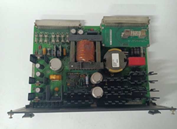
The is a passive, high-voltage signal conditioning board located in the Exciter Auxiliary Cabinet. It is the “G3” variant in the EACF family, designed for systems with high PT secondary voltages (rated up to 1400V RMS).
Physically, it mounts to the cabinet frame (chassis mount). Upstream, it receives raw 3-phase AC from the Generator Potential Transformers (PPTs) and signals from Air Core Current Transformers (CTs) at its screw terminals (TB1-TB4). The board uses internal step-down transformers (T1-T4) to scale and galvanically isolate these high-voltage signals. Downstream, it has no active processing; it fans the conditioned signals out via three 9-pin D-Sub (DB9) connectors (J504 to M1, J509 to M2, J514 to C). This allows the three TMR (Triple Modular Redundant) controllers on the EBKP backplane to independently vote on voltage/current feedback for the AVR (Automatic Voltage Regulator) loop. It is a Level 1/2 interface, critical for maintaining generator terminal voltage stability.
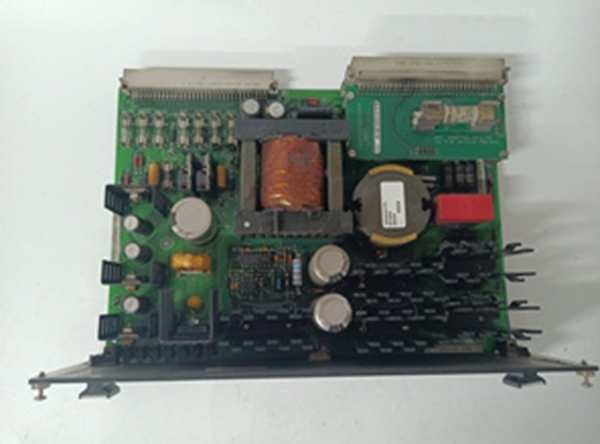
IS200EACFG3B
Core Technical Specifications
- Voltage Rating (G3): 1400V RMS (Nominal +20% transient tolerance)
- Current Inputs: Air Core CT (0 to 0.8V RMS), 2 Terminals (TB4)
- Voltage Inputs: 3-Phase PPT (L1, L2, L3), Terminals TB1, TB2, TB3
- Output Interfaces: 3x DB9 (D-Sub) -> J504 (M1), J509 (M2), J514 (C)
- Transformers: T1, T2, T3, T4 (Signal Scaling & Isolation)
- Test Points: TP1-TP4 (Phase-to-Phase: AB, BC, CA @ Scaled Voltage)
- Power: Passive (No Active Power; Signal Sourced from PT/CT)
- Indicators: None (Blind Board; Diagnostics via Controller/EBKP)
- Coating: Conformal Coated (Revision B)
- Mounting: Chassis Mount (Exciter Aux Cabinet Framework)
- Max Cable Length: Up to 90m (300ft) to EBKP
Customer Value & Operational Benefits
Extreme Voltage Headroom (G3 Rating)
The “G3” (1400V RMS) rating is the defining value. On large turbine-generators (e.g., 500MW+ frames) with high-ratio PPTs, transient overvoltages during system faults can spike well above 1000V. Using a G2 board (1000V) here risks transformer insulation breakdown and flashover. The G3B protects the $20k+ M1/M2/C controllers by acting as a robust first-stage barrier.
TMR Signal Isolation
Like its siblings, it fans out to M1, M2, and C via separate DB9s. The galvanic isolation via T1-T4 means a phase-to-ground fault on the “M1” PPT input (e.g., rodent on wires) will likely only trash the T2 transformer on this board, leaving the M2 and C signal paths intact. This preserves the 2oo3 vote, preventing a spurious “Volts Loss” trip during a grid disturbance.
Centralized Calibration Access
The TP1-TP4 test points provide scaled AC voltage (approx 1.6V AC for 120V PT secondary). You can verify PPT phasing and scaling with a DMM right at the board while synchronized at 100% load, without probing live 13.8kV bushings or pulling EBKP cards. Cuts AVR tuning time significantly.
Field Engineer’s Notes (From the Trenches)
This board is a “Black Box”—zero LEDs. When the AVR starts hunting (VAR oscillation), don’t just swap M1. Grab a Fluke.
Check TP1 to TP2 (Phase A-B). You should see ~1.6V AC (scaled). If TP1-2 reads 0V but your PPT cabinet reads 120V AC, the T2 transformer on the EACFG3B is open (likely cooked by a past lightning surge on the grid).
Critical Warning on Shielding: The DB9 cables (J504 etc.) have shield drains. The ground lug is on the EACF metal chassis, within 3 inches of TB1. Land the shield drain there, not at a distant cabinet ground bar. Running the shield 15 feet to a remote bus creates a ground loop; the 60Hz hum will inject into your AC feedback, causing the generator to “hunt” (oscillate VARs) under heavy load swings.
Also, Torque TB1-TB3. These are PPT inputs. A loose L2 connection causes “Phase Imbalance” or “Volts Mismatch” in the TMR vote. Use a 0.5-0.6 Nm driver; vibration from the exciter fan loosens standard screws over a year.
Real-World Applications
- 800MW Steam Turbine Generator (22kV/13.8kV): The EACFG3B handles PPT secondaries that can see 130V AC nominal, spiking to 150V+ during faults. It scales and isolates these for the M1, M2, C controllers managing the static exciter’s AVR loop.
- Combined Cycle GT (Frame 9FA): Terminating Air Core CT signals (representing DC Field Current as AC). The G3 rating handles the electrical noise from the 6-pulse thyristor bridge switching better than G2, preventing spurious “Field Over Current” trips during transient loading.
IS200EACFG3B
High-Frequency Troubleshooting FAQ
Q: ToolboxST shows “Voltage Feedback Loss” or “PPT Signal Invalid” on M1 only. EACFG3B looks fine. Where’s the fault?
A: The EACF fans out to all three. If only M1 complains, the issue is the DB9 Cable (J504) or the M1’s EBKP receiver, not the EACF board. Wiggle the thumbscrews on J504; vibration loosens these. If tight, ohm the 9-pin cable (Pin 2-3, 4-5, 6-7 for phases). A broken pin 3 kills the A-B voltage signal to M1.
A: Electrically risky. Pinouts are identical, and it will “work” at 120V nominal. However, the G2’s transformer insulation is rated for lower peak transients. If a lightning strike or switching surge hits the grid, the G2’s T2/T3 may arc internally, potentially propagating voltage to the EBKP backplane and frying the M1/M2/C processors. In new installs or major outages, use the specified G3B.
Q: TP1-TP2 reads 0V AC, but PPT secondaries are live at the terminal block. Is the board trash?
A: Likely, yes. Check for a blown fuse (if equipped on specific sub-revs) near T2. If the fuse is good, the T2 transformer winding is open (cooked from a past surge). The EACF is passive; if input power is verified at TB1/TB2 but test points are dead, the board took the hit. Verify no shorts on the PPT field wiring (L1-L2 short) before installing the replacement, or you’ll blow the new T2 in seconds.
Please note: The listed price is not the actual final price. It is for reference only and is subject to appropriate negotiation based on current market conditions, quantity, and availability.


