
Description
System Architecture & Operational Principle
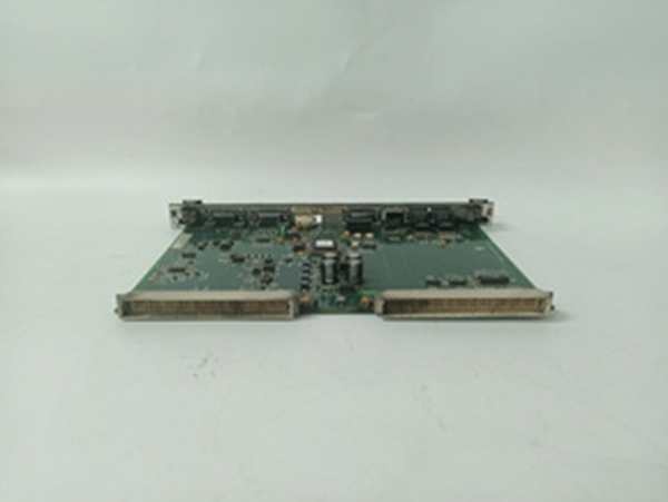
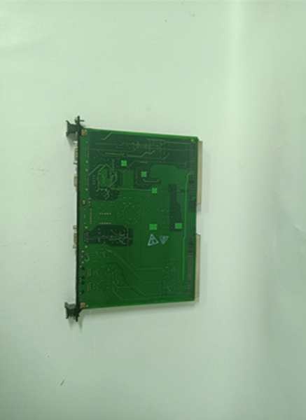
The is a passive signal-conditioning hub located in the Exciter Auxiliary Cabinet. It sits offline from the VME rack, mounting to the cabinet framework, and connects to the EBKP (Exciter Backplane) where the M1, M2, and C controllers reside.
Its job is purely analog interfacing. Upstream, it receives raw AC signals from the Generator Potential Transformers (PPTs)—stepped down to a nominal 1.6V RMS—and Air Core Current Transformers (CTs) (0-0.8V RMS). The board uses internal transformers (T2, T3) to isolate and scale these signals. Downstream, it doesn’t process logic; it “fans out” the conditioned signals via three 9-pin D-Sub (DB9) connectors (J504 to M1, J509 to M2, J514 to C). This allows the three TMR (Triple Modular Redundant) controllers to independently vote on the AC feedback for the AVR (Automatic Voltage Regulator) loop. It operates at Level 1/2, providing the sensory inputs required to regulate generator terminal voltage and VARs.
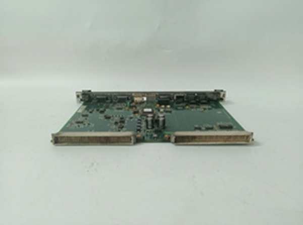
IS200EACFG2B
Core Technical Specifications
- Voltage Rating (G2): 1000V RMS (Nominal +20% tolerance)
- Current Inputs: Air Core CT (0 to 0.8V RMS), 2 Terminals (TB4)
- Voltage Inputs: 3-Phase PPT (L1, L2, L3), Terminals TB1, TB2, TB3
- Output Interfaces: 3x DB9 (D-Sub) -> J504 (M1), J509 (M2), J514 (C)
- Transformers: T2, T3 (Active Signal Conditioning), T1/T4 (Spares/Positions)
- Test Points: TP1-TP4 (Phase-to-Phase: AB, BC, CA)
- Power: Passive (No Active Power Consumption; Signal Sourced from PT/CT)
- Indicators: None (Blind Board; Diagnostics via Controller/EBKP)
- Coating: Conformal Coated (Revision B)
- Mounting: Chassis Mount (Exciter Aux Cabinet Framework)
- Max Cable Length: Up to 90m (300ft) to EBKP
Customer Value & Operational Benefits
High-Voltage Isolation (G2 Rating)
The “G2” designation is the critical differentiator. Rated for 1000V RMS (vs G1’s 480V), this board handles the secondary voltages from PTs on larger gen-sets (e.g., 13.8kV:120V systems where transients spike high). Using a G1 board here risks transformer saturation or arc-over during a system fault/surge. Specifying G2 protects the $20k M1/M2/C controllers from transients on the field wiring.
TMR Signal Integrity
By fanning out via dedicated DB9s to M1, M2, and C, the board ensures galvanic separation of the redundant paths at the sensor level. If a squirrel climbs on the PPT secondary wiring and shorts L1-L2 at the terminal block, the resulting current surge might toast the T2 transformer on thisboard, but it won’t propagate to the M1 processor’s ADC. The M2 and C paths remain viable for the 2oo3 vote.
Centralized Calibration Points
The TP1-TP4 test points allow you to verify PPT phase voltage (e.g., 69.2V L-N) right at the board with a handheld DMM while the unit is synchronized at 100% load. You don’t need to climb into the live PT cabinet. This speeds up AVR tuning and “Volts Mismatch” troubleshooting by 20 minutes per event.
Field Engineer’s Notes (From the Trenches)
This board is a “Blind Horse”—no LEDs. When the AVR goes wonky (hunting VARs), don’t just swap the M1 processor. Grab a Fluke 115.
First, check TP1 to TP2 (Phase A-B). You should see the scaled PPT voltage (approx 1.6V AC for 120V secondary). If TP1-2 reads 0V but your PPT secondary panel reads 120V AC, the T2 transformer on the EACFG2B is open (internal fuse or cooked winding from a past surge).
Second, Shield Drains. The DB9 cables (J504 etc.) have shield drains. The grounding screw is on the EACF metal chassis, within 3 inches of the TB1 terminals. Land the shield there, not at the distant cabinet ground bar. Running the shield drain 10 feet to a remote bus creates a ground loop that injects 60Hz hum into your AC feedback, causing the generator to “hunt” (oscillate VARs) under heavy grid load.
Lastly, Torque TB1/TB2/TB3. These are PPT inputs. A loose L2 connection causes “Phase Imbalance” alarms in the excitation diagnostic. Use 0.5 Nm; vibration loosens these over a 12-month run.
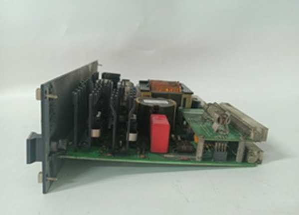
IS200EACFG2B
Real-World Applications
- 500MW Steam Turbine Generator (13.8kV): The EACFG2B receives 120V AC secondaries from the Generator PPTs. It scales and isolates these signals, sending them to M1, M2, and C controllers. This is the primary feedback for maintaining 1.0 PU voltage during a 50MW step-load change.
- EX2100e Static Exciter (Gas Turbine): Terminating the Air Core CT signals (representing DC Field Current as AC). The G2 rating handles the electrical noise from the thyristor bridge switching (6-pulse/12-pulse) better than the G1 variant, preventing spurious “Field Over Current” trips during transient faults.
High-Frequency Troubleshooting FAQ
Q: ToolboxST shows “Voltage Feedback Loss” or “PPT Signal Invalid” on M1 only. EACFG2B looks fine. Where’s the fault?
A: The EACF fans out to all three. If only M1 complains, the issue is the DB9 Cable (J504) or the M1’s EBKP receiver, not the EACF board itself. Wiggle the thumbscrews on J504; vibration loosens these. If tight, ohm out the 9-pin cable (Pin 2-3, 4-5, 6-7 for phases). A broken pin 3 kills the A-B voltage signal to M1.
A: Electrically risky. The pinouts are identical, and it will “work” at 120V nominal. However, the G1’s internal transformers (T2/T3) have lower insulation ratings. If a system fault causes a PT secondary surge (e.g., lightning induced), the G1 board is more likely to flash over, potentially damaging the EBKP backplane and taking out your M1/M2/C controllers. Use G2 for any system >480V nominal.
Q: TP1-TP2 reads 0V AC, but PPT secondaries are live at the terminal block. Is the board trash?
A: Likely, yes. Check Fuse F1 (if equipped on specific sub-revs) near T2. If the fuse is good, the T2 transformer winding is open (cooked from a past surge). The EACF is passive; if input power is verified at TB1/TB2 but test points are dead, the board took the hit. Verify no shorts on the PPT field wiring (L1-L2 short) before installing the replacement, or you’ll blow the new T2 in seconds.
Please note: The listed price is not the actual final price. It is for reference only and is subject to appropriate negotiation based on current market conditions, quantity, and availability.


