
Description
System Architecture & Operational Principle
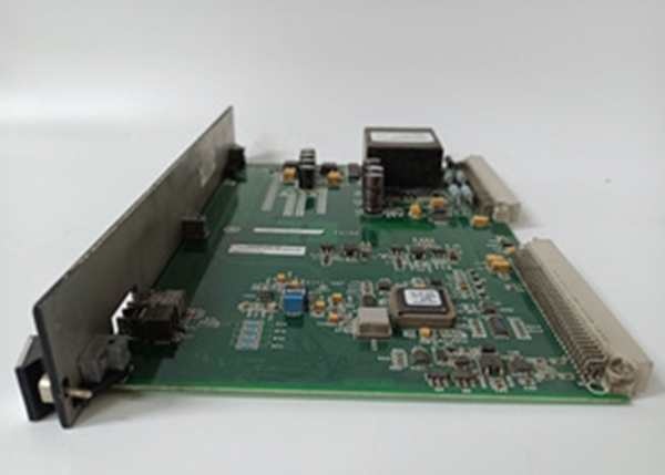
The is a passive signal conditioning and distribution board located in the Exciter Auxiliary Cabinet. It sits between the high-voltage AC field sensors and the active control processors (M1, M2, C).
Upstream, it receives raw AC signals from the Potential Power Transformer (PPT) for generator voltage feedback and Air Core Current Transformers (CTs) for field current measurement. Downstream, it doesn’t process logic itself; it acts as a signal hub. The board utilizes internal transformers (T2, T3) to step down voltages and isolate signals. It fans these conditioned signals out through three 9-pin D-sub (DB9) connectors (J504, J409, J514), sending identical data streams to the M1, M2, and C controller stacks respectively. This allows each controller in the TMR (Triple Modular Redundant) set to vote on the AC feedback independently. It typically interfaces with the EBKP (Exciter Backplane) where the M1/M2/C processors reside, acting as the sensory front-end for the AVR (Automatic Voltage Regulator) loop.
IS200EACFG1B
Core Technical Specifications
- Signal Inputs: AC Voltage (PPT), AC Current (Air Core CT)
- Voltage Rating: Up to 480V AC RMS (G1 Group Designation)
- Output Interfaces: 3x DB9 (D-Sub) Connectors (For M1, M2, C Links)
- Transformer Blocks: T2, T3 (Active), T1, T4 (Omitted/Spare positions)
- Flux Coil Terminals: 2 Terminals (For Air Core/Flux feedback loops)
- Coating: Standard Conformal Coating (Revision B)
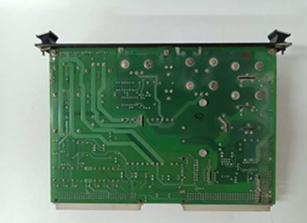
- Mounting: Chassis Mount (Exciter Aux Cabinet Framework)
- Key Test Points: TP1-TP4 (Phase-to-Phase Voltage Checks: AB, BC, CA)
- Isolation: Galvanic isolation via onboard step-down transformers
- Environmental: 0°C to +60°C (Typical Exciter Cabinet Ambient)
Customer Value & Operational Benefits
TMR Signal Integrity
The board’s primary value is signal replication without loading. By using the onboard transformers (T2/T3) and fan-out DB9s, it ensures the M1, M2, and C controllers see identical AC waveforms. This preserves 2oo3 voting accuracy in the excitation loop. If a cable to ‘M1’ fails, ‘M2’ and ‘C’ still have valid, isolated signals, preventing a spurious generator trip during a grid disturbance.
Physical Accessibility for Calibration
Unlike rack-mounted VME cards buried behind doors, the EACF is chassis-mounted in the auxiliary cabinet with test points (TP1-TP4) exposed. You can stick a fluke on TP1 to TP2 (VAB) to verify PPT scaling while the unit is synchronized at 13.8kV without pulling any active processor cards. This cuts troubleshooting time for “Volts Mismatch” alarms by 30 minutes per event.
Noise Rejection in HV Environment
The G1 design and transformer isolation block common-mode noise from the thyristor switching in the main exciter bridge (located nearby). Clean AC feedback is critical; dirty voltage signals here cause AVR instability (VAR oscillation), which can trip the generator on “Over/Under Excitation” limits.
Field Engineer’s Notes (From the Trenches)
The “Gotcha” on the EACF series is transformer phasing and terminal torque. The PPT inputs (L1/L2/L3) are high impedance; a loose screw on the PPT block creates an open-circuit “glitch” that the AVR interprets as a 50% voltage swing, causing the field to surge.
Always meg-ohm the PPT secondaries before landing wires on the EACF. If the PPT failed (shorted turn), it will cook the T2/T3 transformers on this board in minutes.
Also, cable shielding: The DB9 cables to M1/M2/C are shielded. The drain wire terminates on a specific shield screw on the EACF frame (within 3 inches of the inputs). If you land that shield to the cabinet ground bar 10 feet away instead of the board’s frame lug, you create a ground loop that injects 60Hz hum into the AC feedback, making the VARs hunt. Use the local shield screw, not the remote bus.
IS200EACFG1B
Real-World Applications
- Steam Turbine Generator AVR: The EACFG1B receives 120V AC secondary from the Generator PPT (13.8kV:120V). It scales this via T2/T3 and sends it to M1, M2, C controllers. This is the primary feedback for the “Volts Regulator” loop maintaining 1.0 PU voltage during load swings.
- EX2100 Bridge Current Monitoring: Terminating the Air Core CT signals (representing DC Field Current as AC). The board conditions these for the “Current Regulator” loop, ensuring the exciter doesn’t over-current the rotor during a fault clearance.
High-Frequency Troubleshooting FAQ
Q: ToolboxST shows “Voltage Feedback Loss” or “PPT Signal Invalid” on M1 only. EACFG1B looks fine. What’s wrong?
A: Check the DB9 Cable (J504 for M1). The EACF fans out to all three controllers; if only M1 complains, the issue is the cable or the M1’s EBKP receiver, not the EACF board itself. Wiggle the DB9 connector at the EACF end—vibration loosens these thumbscrews. If tight, verify continuity pin-to-pin on the 9-conductor cable; a broken pin 2 or 3 kills the AC signal to that controller.
A: Physically, yes. The “B” revision is a direct replacement for “A” with likely component updates (tighter tolerances, coating differences). Electrically and pin-out wise, they are interchangeable. Just ensure your PPT input voltage is within the G1 spec (<480V RMS). If you have a G2 board (handles higher volts) and try to put a G1 (B) in its place on a 600V system, you risk satururing the onboard transformers.
Q: Measuring TP1 to TP2 shows 0V, but PPT secondary has 120V AC at the terminal strip.
A: You likely have a blown trace or failed fuse on the EACF board, or the T2/T3 transformer has an open winding (often from a PPT primary fault). The EACF is passive; if input power is verified at the screw terminals but test points are dead, the board took the hit. Check the fuse (if equipped) near the T2 block; otherwise, the PCB trace from the terminal to T2 has likely vaporized—board replacement required.
Please note: The listed price is not the actual final price. It is for reference only and is subject to appropriate negotiation based on current market conditions, quantity, and availability.


