
Description
Hard-Numbers: Technical Specifications
- PPT Input Voltage: 480 Vrms (50/60 Hz, ±20%)
- Transformer Secondary Output: Nominal 1.6 Vrms
- Flux Coil (CT) Input: 0 to 0.8 Vrms
- Backplane Cable Length Limit: 295 ft (90 meters)
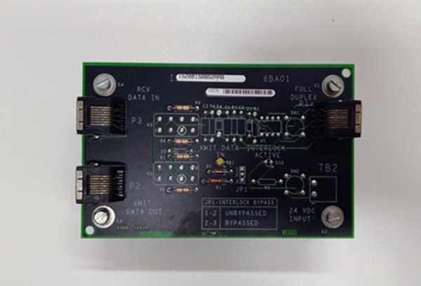
- Connectors: 3x 9-pin D-sub (M1, M2, C Controllers)
- Terminal Blocks: 4x (TB1-TB4)
- Operating Temperature: -40°C to +70°C
- Shield Grounding Point: Within 3 inches (76mm) of entry
- Isolation Rating: 1500 VAC channel-to-chassis
GE IS200EACFG1A
The Real-World Problem It Solves
You’re troubleshooting a 9FA gas turbine that keeps tripping on “Field Overvoltage” during grid transients. The old analog metering can’t keep up with the 60Hz ripple, and the noise from the 4160V switchgear is drowning out the feedback signal. This EACF board solves that mess. It takes the raw 480V PPT and flux coil signals, isolates them, and drops them down to a clean 1.6Vrms that the M1 controller can actually read without throwing false alarms.
Where you’ll typically find it:
- EX2100 Exciter Cabinets: Mounted in the auxiliary cabinet, bridging the gap between the PPTs and the main control rack.
- Large Steam Turbine Generators: Providing real-time feedback for automatic voltage regulators (AVR).
- Power Plant Retrofits: Replacing obsolete hard-wired PT/CT cabinets with a compact, standardized terminal board.
It turns a noisy, high-voltage feedback loop into a stable, deterministic signal for your excitation control.
Hardware Architecture & Under-the-Hood Logic
This isn’t a smart I/O card; it’s a passive, high-precision signal interface. It has no microprocessor. Its job is to survive the brutal electrical environment of a power generation plant and protect the expensive M1/M2 controllers from high-voltage transients.
- Voltage Step-Down & Isolation: The 480V PPT inputs hit three onboard transformers. These knock the voltage down to a safe 1.6Vrms while providing galvanic isolation between the high-voltage field and the 24V control logic.
- Flux Coil Signal Conditioning: The weak 0-0.8Vrms signal from the air-core current transformer (Flux Coil) passes through an RC filter network. This strips out the high-frequency switching noise from nearby thyristors before the signal reaches the controller.
- Signal Fan-Out: The conditioned signals are duplicated across three 9-pin D-sub connectors. This allows one set of field wiring to feed the primary M1 controller, the redundant M2 controller, and the C controller simultaneously.
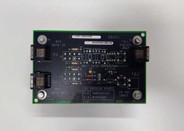
GE IS200EACFG1A
Field Service Pitfalls: What Rookies Get Wrong
Ignoring the 3-Inch Shield Grounding Rule
A rookie lands the shielded twisted pair from the flux coil and ties the shield to the nearest ground point five feet away. The turbine runs fine until a 6kV breaker closes nearby. The induced EMI travels along the shield and spikes the M1 controller, causing a nuisance trip.
- Field Rule: Ground the cable shield within 3 inches (76mm) of the terminal block. Use a 360-degree clamp or a star washer to ensure a low-impedance connection to the board’s chassis ground. Never let the shield float.
Using the Wrong Voltage Revision (G1 vs. G2/G3)
A tech replaces a fried IS200EACFG1A with a G2 version (designed for 1000V systems) because it’s on the shelf. The system calibrates fine at no-load, but during a 90% load ramp, the secondary voltage is too low for the controller to accurately read, causing the AVR to hunt and oscillate.
- Quick Fix: Match the primary voltage rating exactly. If your PPTs are 480V, use G1. If they are 1000V, use G2. If they are 1300V, use G3. Using the wrong turns ratio will ruin your voltage regulation.
Exceeding the 90-Meter Backplane Cable Limit
During a plant expansion, the exciter cabinet was moved 400 feet away from the main control room. The rookie runs a long cable to connect the EACF board to the M1 controller. The signal degrades over the distance, and the controller frequently reports “Feedback Loss” during high-vibration events.
- Field Rule: The cable length between the EACF and the M1/M2/C controllers must not exceed 90 meters (295 ft). If you need to go further, install a fiber-optic media converter or relocate the control rack. Do not try to stretch the limit; capacitance will kill the signal integrity.
Commercial Availability & Pricing Note
Please note: The listed price is for reference only and is not binding. Final pricing and terms are subject to negotiation based on current market conditions and availability.


