
Description
Product Introduction
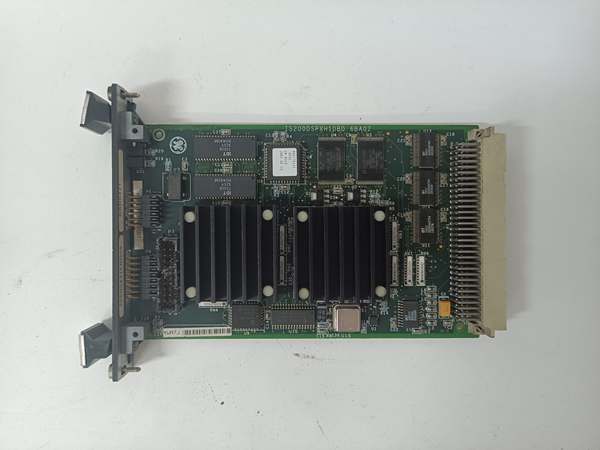
The GE is a dedicated DSP control board acting as the computational engine for Mark VIe systems, handling intensive math for vibration analysis and excitation regulation. It mounts in the VME rack, offloading FFT calculations from the main CPU to maintain sub-20 ms response times on critical protection loops.
This “H1DBD” revision integrates a 60 MHz processor with an ASIC co-processor for deterministic execution. It communicates via the backplane to VVIB and ERIO packs. The unit handles 64+ channels of data acquisition, filtering noise down to 0.1% THD in high-EMI turbine compartments .
IS200DSPXH1DBD
Key Technical Specifications
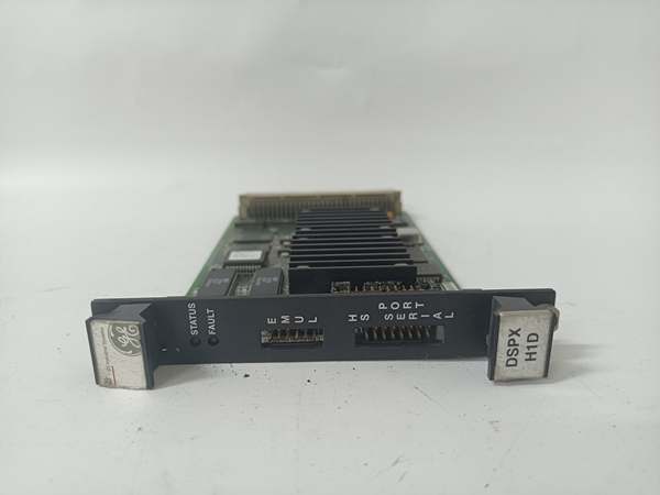
- System Role: DSPX (Digital Signal Processor Expansion)
- Processor: 60 MHz Digital Signal Processor + ASIC
- Architecture: 32-bit (Floating Point capable)
- Logic Power: 24 Vdc / 28 Vdc (From VME Backplane)
- Power Draw: ~10 W (Typical, verify with OEM datasheet)
- Sampling Rate: Up to 25 kHz (Analog Inputs)
- Memory: Flash (Firmware), NVRAM (Configuration)
- Indicators: Status LED, Fault LED (Front Panel)
- Connectors: P1/P2 (VME Backplane), P5/P6 (Aux/Debug)
- Temp Range: -30 °C to +65 °C (Operational)
- Coating: Conformal Coated (H1 Revision standard)
Quality Control Process (Engineer’s Perspective)
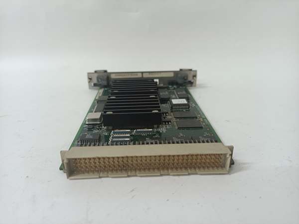
- Incoming Verification: Match the GE serial to the manifest. Inspect the 96-pin DIN fingers for carbon scoring—arcing leaves permanent marks. Check the ASIC chip for hairline cracks under magnification.
- Live Functional Test: Seat in a VME test rig with 24 Vdc. Run a synthetic FFT workload; we monitor the Status LED for steady blink. Scope the P2 data lines; timing skew must stay under 5 µs under 80% load.
- Electrical Parameter Test: Back-probe the 24 Vdc rail with a Fluke 115. Megger the backplane connectors to chassis at 500 V; leakage must hold >10 MΩ to survive exciter transients.
- Firmware Verification: Read the DSP code version via ToolboxST. Photograph the boot jumper (if present)—well, technically most is flash-based now, but a “Boot Mode” strap can brick the ASIC init.
- Final QC & Packaging: Clean DIN fingers with isopropanol. Bag in rigid ESD foam (6U boards are heavy). Label “QC Passed – DSP Stress Test” with the date.
Replacement Pitfall Guide
❗ TMR Uniformity: The GE is often used in triplets (R, S, T). Mixing this “DBD” revision with an older “DBC” in the same rack causes “Processor Mismatch” votes and forces the protection to trip or degrade.
❗ Backplane Seating: The 96-pin P1/P2 connectors are tight. “Half-seating” P2 while P1 is home bends the pins on the adjacentboard. Apply even pressure until both ejector levers lock—check the visual alignment markers.
❗ ASIC Initialization: This board relies on the ASIC for crunching control laws. A corrupted firmware load (.dspfile) results in “DSP Fault” LEDs that won’t clear without a specific rescue boot procedure via the P5 header.
❗ Heat Soak: The 60 MHz DSP generates heat. In cabinets with failed ventilation, sustained temps above 65 °C age the NVRAM batteries in 6 months—check the VME rack’s ambient temp before racking.
❗ ESD to Pins: The DIN fingers are dense. Discharge to the VME chassis before insertion—critical in dry shops (common in northern China winters).
Keep these in mind and you’ll cut 90% of rework time.
IS200DSPXH1DBD
Compatibility Matrix & Benchmarks
- GE → GE IS200DSPXH1DBC : Needs Adaptation — DBD is newer; verify TMR triplet uniformity in ToolboxST.
- GE → GE VVIB / ERIO (Packs) : Direct — Processes data sourced from these I/O boards.
- GE → Standard VME CPU : Incompatible — Custom ASIC for Turbine Control Algorithms.
- FFT Execution: < 20 ms (1024-point transform)
- Data Throughput: 5 Mbps (Backplane to VME Bus)
- Sampling Jitter: < 1 µs (Clock stability, verify with OEM datasheet)


