
Description
Product Introduction
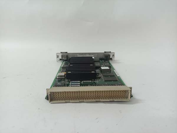
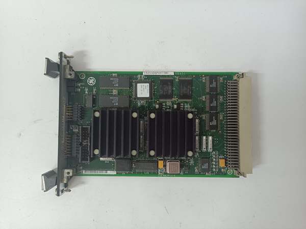
The GE is a computational workhorse for Mark VI and EX2100 systems, offloading complex math (FFT, PID) from the main controller to maintain sub-20 ms loop times. It mounts in the VME rack, interfacing directly with I/O packs via the P1/P2 backplane connectors.
This “DBC” revision integrates a 60 MHz processor with a custom ASIC for deterministic logic execution. It handles 32-bit data paths and includes Status/Fault LEDs on the front panel. Power draw sits around 10 W typical, running steady from -30 to +65 °C .
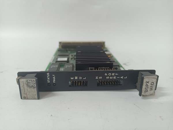
IS200DSPXH1DBC
Key Technical Specifications
- Processor: 60 MHz Digital Signal Processor (DSP)
- Coprocessor: Application-Specific Integrated Circuit (ASIC)
- Logic Voltage: +5 V DC (Primary), +24 V DC (Aux/Logic, verify with OEM datasheet)
- Power Draw: ~10 W (Typical operating load)
- Memory: FLASH (Boot/App), RAM (Runtime), NVRAM (Retentive Data)
- Connectors: P1/P2 (VME Backplane), P5 (Emulator), P6 (Engineering Monitor)
- Indicators: 2 LEDs (Green Status, Red Fault)
- Form Factor: 6U VME (Double Height)
- Coating: Conformal Coated (DBC Revision)
- Temp Range: -30 °C to +65 °C (Operational)
- Interfaces: ISBus (5 Mb/s), Serial (TTL)
Quality Control Process (Engineer’s Perspective)
- Incoming Verification: Match the GE serial to the manifest. Inspect the 96-pin DIN fingers for carbon tracks—arcing leaves permanent scars. Check the ASIC chip for hairline cracks under 10x loupe.
- Live Functional Test: Seat in a VME test rig with 5 V/24 V. Run a synthetic FFT workload; monitor the Green LED for steady blink. We scope the P2 data lines; timing skew must stay under 5 µs at 80% load.
- Electrical Parameter Test: Back-probe the 5 V rail with a Fluke 115. Ripple shouldn’t exceed 50 mV p-p. Megger the backplane connectors to chassis at 500 V; leakage >10 µA risks noise issues.
- Firmware Verification: Read the DSP code version via ToolboxST. Photograph the boot jumpers (if present)—well, technically most is flash-based, but a “Boot Mode” strap can halt ASIC init.
- Final QC & Packaging: Clean DIN fingers with isopropanol. Bag in rigid ESD foam (6U is heavy). Label “QC Passed – DSP Stress Test” with the date.
Replacement Pitfall Guide
❗ TMR Uniformity: The GE is often used in triplets (R, S, T). Mixing this “DBC” with an “DBD” in the same rack causes “Processor Mismatch” votes and forces protection degradation.
❗ Backplane Seating: The 96-pin P1/P2 are tight. “Half-seating” P2 bends pins on the adjacentboard. Apply even pressure until both ejector levers lock—check the visual alignment markers on the bracket.
❗ ASIC Dependencies: This board relies on the ASIC for control laws. A corrupted .dspfile results in “DSP Fault” LEDs that won’t clear without a P5 header rescue boot—have the recovery file ready.
❗ 5V Rail Sag: The DSP pulls significant current on the 5 V line. In aging VME racks (VSPA PSU), voltage dipping below 4.75 V causes random resets during turbine run-up.
❗ ESD to Fingers: The DIN pins are dense. Discharge to the VME chassis before insertion—critical in dry shops (common in northern China winters).
Keep these in mind and you’ll cut 90% of rework time.
IS200DSPXH1DBC
Compatibility Matrix & Benchmarks
- GE → GE IS200DSPXH1DBD : Needs Adaptation — DBC is coated rev; verify TMR triplet uniformity in ToolboxST.
- GE → GE VVIB / ERIO (Packs) : Direct — Processes data sourced from these I/O boards.
- GE → Standard VME CPU : Incompatible — Custom ASIC for Turbine/Exciter Algorithms.
- FFT Execution: < 20 ms (1024-point transform)
- Data Throughput: 5 Mbps (ISBus Backplane)
- Stability: 60 MHz (Clock jitter < 1 µs)


