
Description
System Architecture & Operational Principle
The lives in the VME rack of a GE Mark VI or EX2100 system, typically occupying a dedicated slot (often Slot 2 or 3) in the Controller Core (R, S, or T). It sits on the P1/P2 backplane, drawing +5V DC and communicating with the main processor (UCVE/VCGC) and I/O boards (ERIO, VVIB).
Upstream, it receives raw digitized data (generator voltage/current, speed pulses) via the VMEbus. Downstream, it executes the heavy computational lifting: FFT for vibration analysis, PID loops for AVR (Automatic Voltage Regulator), and gate firing calculations for thyristor bridges. The integrated ASIC (Application-Specific Integrated Circuit) handles deterministic tasks like pulse generation for the exciter firing circuit, ensuring the 60 MHz DSP isn’t interrupted by interrupts. In TMR (Triple Modular Redundant) setups, three of these boards run in parallel; this unit participates in hardware voting to mask single-point failures. It operates at Level 2 (Control) of the Purdue Model.
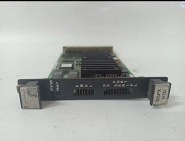
IS200DSPXH1D
Core Technical Specifications
- Processor: 60 MHz Digital Signal Processor (DSP)
- Coprocessor: Custom ASIC (Deterministic Control/Firing Logic)
- Memory: FLASH (Firmware), RAM (Runtime), NVRAM (Retentive Vars)
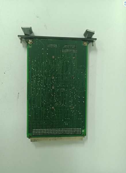
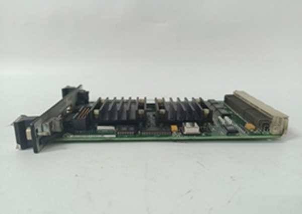
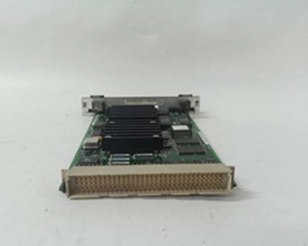
- Backplane Interface: 96-pin DIN 41612 (P1 Primary, P2 I/O Expansion)
- Front Ports: P5 (DSP Emulator/JTAG), P6 (Engineering Monitor/RS-232)
- Logic Voltage: +5 V DC (Primary), +12/-12 V DC (Aux/Indicators)
- Power Dissipation: ~10-15W (Requires adjacent slot airflow)
- Indicators: STATUS (Green/Activity), FAULT (Red/Diagnostic)
- Form Factor: 3U VME (Single-height, approx 100mm x 160mm)
- Environmental: 0°C to +60°C (Operational)
- Isolation: 1500 Vrms (Logic to I/O boundaries via backplane)
Customer Value & Operational Benefits
Computational Offloading
The DSPX is the math coprocessor for the turbine. By crunching FFT (Vibration) and Excitation PID locally, it prevents the main UCVE CPU from bogging down during transient events (e.g., generator load rejection). This keeps control loop scan times deterministic (sub-20ms), which is non-negotiable for generator stability and avoiding AVR instability during grid disturbances.
TMR System Integrity
In a Triple Modular Redundant configuration, this board is designed for 2oo3 (Two-out-of-Three) Voting. If a cosmic ray flip or hardware glitch hits the DSP on the ‘R’ core, the ASIC logic ignores the faulty node. This allows the unit to keep running (degraded/Simplex) instead of tripping on a single component failure, directly protecting MTBF and avoiding unplanned outage costs (easily $50k+/hour on heavy frames).
Firing Precision
The ‘H1D’ revision’s ASIC is tuned for Thyristor Firing Pulses in EX2100 systems. Replacing an older revision with ‘H1D’ often resolves historical timing skew issues in bridge firing, reducing thyristor stress and equalizing commutating reactor current distribution.
Field Engineer’s Notes (From the Trenches)
Never hot-swap this board unless the manual explicitly confirms hot-swap capability for this specific revision (usually it doesn’t). The 96-pin P1/P2 carries +5V at high current. Sliding this out live risks arc flash between pins; sliding it in can cause a voltage sag on the backplane, resetting the adjacent UCVE processor. LOTO the EPSM for that core.
Inspect the BGA (Ball Grid Array) under the main DSP chip if the “FAULT” LED is on but the board is cool. After 15+ years of thermal cycling in a hot cabinet, those solder balls crack. A thermal camera will show the chip staying cold while the surrounding regs heat up—classic BGA fracture.
Also, the ‘D’ revision implies specific timing tolerances. If mixing ‘H1D’ with ‘H1A’ or ‘H1B’ in a TMR triplet, watch for Vote Timing Skew in ToolboxST. The propagation delays differ slightly between revisions; if alarms pop during “TMR Align,” you likely have a mixed-revision set. Stick to matching H1D across R, S, T.
IS200DSPXH1D
Real-World Applications
- EX2100 Excitation Control: The board processes Generator PT (Voltage) and CT (Current) data to calculate the AVR error signal. It drives the firing angle pulses sent to the ERIO board, regulating DC field current on a 500MW Steam Turbine Generator.
- Mark VI Vibration Monitoring: Paired with VVIB I/O packs, this DSPX runs 1X/2X Order Tracking on the 4-20mA proximity probe data from Gas Turbine bearings. It detects subsynchronous resonance or rubs, triggering “Alert” setpoints before a catastrophic rub occurs.
High-Frequency Troubleshooting FAQ
A: 90% of the time, this is a Firmware/Application Mismatch or Memory Parity Error. The board has +5V power (hence no power LED issues), but the bootloader failed the POST (Power-On Self-Test). Connect a terminal to the P6 (COM4) port using a null-modem cable. You’ll likely see “Code/Config Mismatch” or “NVRAM Checksum Fail.” You need to download the correct .applfile for the H1D hardware rev via ToolboxST.
A: Physically, yes (both 3U VME). Functionally, check your system type. The ‘DBO’ is often associated with Innovation Series drives or specific EX2100e updates, potentially having different ASIC configurations for firing sequences. In a standard Mark VI EX2100 rack, stick to H1D. Mixing them in a TMR set will cause “Architecture Mismatch” alarms and vote failures.
Q: ToolboxST shows “Processor Not Responding” on the VME Bus after install.
A: P1 Connector Seating. The 96-pin DIN is tight. If the ejector levers aren’t fully latched, the bottom row (P1/P2) won’t mate. Remove, inspect pins for carbon tracking (sign of a previous surge), clean with 90% Iso, and re-insert with even pressure on both ejectors. Also, verify the VME Bus Terminator (resistor pack at the end of the backplane) is seated; an unterminated bus kills DSPX comms instantly.
Please note: The listed price is not the actual final price. It is for reference only and is subject to appropriate negotiation based on current market conditions, quantity, and availability.


