
Description
Hard-Numbers: Technical Specifications
- Bridge Compatibility: 1000 Amp and 1800 Amp PWM Source Bridges
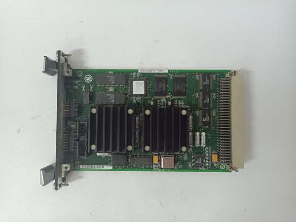
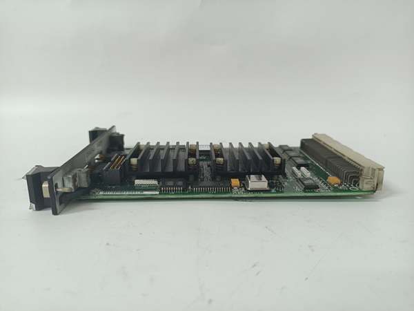
- Current Sensing: Built-in precision shunt resistor for real-time feedback
- Surge Protection: 1x Circular Red MOV (Metal Oxide Varistor)
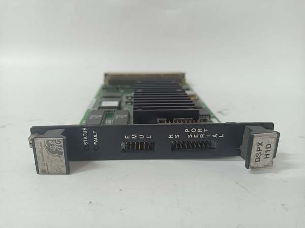
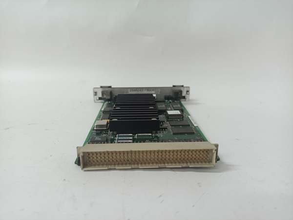
- Physical Dimensions: 6.5 inches x 7 inches (approx. 165mm x 178mm)
- Mounting Style: DIN-rail mountable
- Isolation Rating: Galvanic and Optical Isolation between driver and feedback circuits
- Configuration Jumpers: 6 Pins (PL, PL1, PL2)
- Connector Count: 13 total (3x 9-bit, 7x 2-bit, 3x 6-bit)
- Operating Temperature: -40°C to +70°C
The Real-World Problem It Solves
You’re staring down a 9F-class gas turbine drive train, and the massive 1800 Amp source bridge is screaming for clean, instantaneous current feedback. Standard feedback cards can’t handle the electrical noise and massive transient spikes generated by a 4160V VFD. This DSFC board is the heavy lifter. It clamps incoming voltage spikes with a dedicated MOV and measures the precise current flowing through the bridge using an onboard shunt resistor, delivering rock-solid data to your Mark VI controller without blowing up downstream electronics.
Where you’ll typically find it:
- Large Combined-Cycle Generating Units: Mounted on 1000A or 1800A PWM source bridges controlling the main generator exciter or large boiler feed pumps.
- Innovation SeriesTM Drive Cabinets: Serving as the primary interface between the drive bridge personality board and the Mark VI control system.
- Retrofit Projects: Replacing obsolete analog feedback sensors in heavy industrial AC drive applications.
It turns a chaotic, high-current power conversion environment into a stable, measurable, and highly protected control loop.
Hardware Architecture & Under-the-Hood Logic
This isn’t a passive interface; it’s an active signal conditioner and protector living on the edge of a high-power electrical grid. It takes the raw, terrifying electrical energy from the source bridge and turns it into digestible data for your control system.
- Shunt Resistor Measurement: The heart of the board is the precision shunt resistor. As thousands of amps flow through the bridge, a proportional millivolt signal is generated across this resistor. The board amplifies this signal, making it readable by the Mark VI I/O packs.
- Transient Suppression (The Red MOV): Located in the upper-left corner, the circular red Metal Oxide Varistor (MOV) acts as a pressure relief valve. If a lightning strike or an inductive kickback sends a voltage spike down the line, the MOV instantly diverts that excess energy to ground, saving the sensitive control electronics.
- Galvanic and Optical Isolation: The driver circuits and feedback circuits are physically and electrically isolated from each other. This prevents the massive ground loops and electrical hash from the 1800A bridge from corrupting the 24VDC logic signals coming from the Mark VI controller.
- Customizable Jumper Logic: Six jumper pins (PL, PL1, PL2) allow field engineers to tailor the board’s gain, bias, and fault detection thresholds to match the specific characteristics of the connected AC drive or source bridge.
Field Service Pitfalls: What Rookies Get Wrong
Forgetting to Set the Gain/Bias Jumpers
A rookie swaps a dead DSFC board with a new one from the warehouse. They bolt it in, turn on the power, and the turbine immediately trips on “Bridge Overcurrent.” The jumpers on the new board are set to the factory default, which doesn’t match the gain and bias requirements of your specific 1800A source bridge.
- Field Rule: Photograph the jumper configuration of the failed board before removal. Replicate those exact jumper settings (PL, PL1, PL2) on the replacement board. If the photo is blurry, consult the specific drive cabinet wiring diagram for the jumper map.
Mounting the Board Too Close to the IGBT Heat Sink
A tech installs the DSFC board directly against the 1000A IGBT module’s heat sink to save space. During a full-load transient, the IGBT heat sink hits 90°C. The radiant heat soaks into the DSFC board, causing the precision shunt resistor to drift out of tolerance and throwing wildly inaccurate current readings.
- Quick Fix: Maintain a minimum 75mm (3-inch) air gap between the DSFC board and any high-wattage heat-generating components. If space is tight, install a small 24VDC “muffin fan” to create active airflow across the DSFC’s shunt resistor and MOV components.
Using Standard Wire Gauge for Shunt Connections
An engineer lands the massive power cables from the source bridge to the DSFC board using standard #14 AWG wire because it’s what’s available in the truck. The high current causes the small-gauge wire to overheat, increasing resistance and leading to a dangerous voltage drop across the shunt measurement circuit.
- Field Rule: Always use the manufacturer-specified wire gauge for the shunt resistor connections (typically #2 AWG to 4/0 AWG depending on the bridge rating). Crimp high-quality compression lugs onto the ends. Torque the lugs to spec and apply a thin coat of anti-oxidizing compound to prevent corrosion.
Commercial Availability & Pricing Note
Please note: The listed price is for reference only and is not binding. Final pricing and terms are subject to negotiation based on current market conditions and availability.


