
Description
Key Technical Specifications
-
Model Number: IS200CABPG1BAA
-
Manufacturer: General Electric (GE) – Industrial Solutions
-
Backplane Function: VME-style interconnect for IS200 boards; carries +5 V, ±12 V, 28 V, ISBus coax, and discrete I/O
-
Isolation: 2 kV basic board-to-board; ISBus transformer-coupled LAN segment
-
Temperature Range: –30 °C…+65 °C operational
-
Dimensions: 8.5 × 11 in (standard Mark VI card-footprint), 1.4 kg typical
-
Connectors: 96-pin DIN 41612 rows (power & logic), coax F-type for ISBus, keyed card-slots to prevent mis-insertion
-
Mounting: Horizontal card-file rails; four corner stand-offs
-
Protection Degree: IP20 (rack interior)
-
Status: Factory discontinued – new & tested spares available
Field Application & Problem Solved
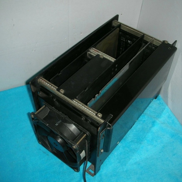
Inside a Mark VI or EX2100 exciter rack the biggest headache is keeping thirty-odd IS200 boards talking to each other without plugging a card into the wrong slot and shorting the 28 V logic bus. The IS200CABPG1BAA solves that by giving every daughter-card a keyed slot and a dedicated ISBus coax segment. You’ll typically find it on the left-hand card-file of EX2100 exciter sections—one backplane feeds power, LAN, and I/O to all boards, and if you crack a coax connector the whole LAN segment drops, so swap time is five minutes with the unit on turning gear. Core value: it collapses a VME back-plane, ISBus hub, and mechanical keying system into one 1.4 kg plate you can swap without rewiring the cabinet

Inside a Mark VI or EX2100 exciter rack the biggest headache is keeping thirty-odd IS200 boards talking to each other without plugging a card into the wrong slot and shorting the 28 V logic bus. The IS200CABPG1BAA solves that by giving every daughter-card a keyed slot and a dedicated ISBus coax segment. You’ll typically find it on the left-hand card-file of EX2100 exciter sections—one backplane feeds power, LAN, and I/O to all boards, and if you crack a coax connector the whole LAN segment drops, so swap time is five minutes with the unit on turning gear. Core value: it collapses a VME back-plane, ISBus hub, and mechanical keying system into one 1.4 kg plate you can swap without rewiring the cabinet
IS200CABPG1BAA
.
Installation & Maintenance Pitfalls (Expert Tips)
Coax F-Connectors Crack—Torque 1 Nm Only
The ISBus coax bulkheads are brass—over-tighten and the threads strip. Use a 7/16 wrench and stop when the collar seats; then tug-test the cable. A loose F-connector gives “LAN timeout” that looks like a board failure.
The ISBus coax bulkheads are brass—over-tighten and the threads strip. Use a 7/16 wrench and stop when the collar seats; then tug-test the cable. A loose F-connector gives “LAN timeout” that looks like a board failure.
Card Slots Are Keyed—Don’t Force a Board
Each daughter-card slot has a unique key peg; if you file it off to “make it fit” you’ll plug a 28 V coil driver into a 5 V logic row and blow the back-plane. Match the key code on the card edge to the slot before you push.
Each daughter-card slot has a unique key peg; if you file it off to “make it fit” you’ll plug a 28 V coil driver into a 5 V logic row and blow the back-plane. Match the key code on the card edge to the slot before you push.
Backplane Screws Must Be Even—Or the Busses Arc
The four corner stand-offs carry ground and +28 V. If you tighten one corner first the board rocks and the inner layers can short. Snug all four screws finger-tight, then torque in a cross-pattern to 1 Nm.
The four corner stand-offs carry ground and +28 V. If you tighten one corner first the board rocks and the inner layers can short. Snug all four screws finger-tight, then torque in a cross-pattern to 1 Nm.
Spare Lead-Time Is 6-8 Weeks—Keep One on the Shelf
Factory stock is gone; new & tested spares are available but not overnight. If you crack a coax or burn a layer you’ll be down until the part arrives—keep one in stores or you’ll discover the weakness during the next forced outage
Factory stock is gone; new & tested spares are available but not overnight. If you crack a coax or burn a layer you’ll be down until the part arrives—keep one in stores or you’ll discover the weakness during the next forced outage
.
Technical Deep Dive & Overview
Internally the backplane is a ten-layer PCB with power planes for +5 V, ±12 V, and +28 V, plus a 75 Ω coax bus for ISBus LAN. Each card slot has a keyed 96-pin DIN connector; the inner rows carry logic, the outer rows carry power, and the coax F-type feeds the LAN segment. Lose a coax and the whole LAN ring drops; lose a power plane and every card in that row browns out. No firmware—pure hardware—so you can swap it without reloading parameters; just remember to torque the coax nuts or the LAN will fault on the first packet.
Internally the backplane is a ten-layer PCB with power planes for +5 V, ±12 V, and +28 V, plus a 75 Ω coax bus for ISBus LAN. Each card slot has a keyed 96-pin DIN connector; the inner rows carry logic, the outer rows carry power, and the coax F-type feeds the LAN segment. Lose a coax and the whole LAN ring drops; lose a power plane and every card in that row browns out. No firmware—pure hardware—so you can swap it without reloading parameters; just remember to torque the coax nuts or the LAN will fault on the first packet.


