
Description
Hard-Numbers: Technical Specifications
-
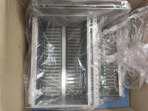
Backplane Connectors: 21× female VME connectors (rear side, for board insertion)
-
I/O Connectors: 39× connectors (front side, for ribbon cable wiring)
-
Rack Compatibility: Designed for 259B2460BTG2 protection rack system
-
Board Dimensions: 17.8 cm (W) × 33.02 cm (H) × 6.35 cm (D)
or 11.0″ × 8.5″ × 2.5″
-
Weight: 1.2 kg (2.65 lbs)
to 0.44 kg
-
Mounting: Rack-mounted with retention borders that lock boards into place
-
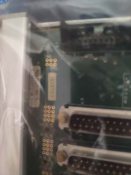
Material: FR4 PCB with gold-plated VME connectors
-
Operating Temperature: -30°C to +60°C (inferred from Mark VI series)
-
Power: Passive distribution only—no active power conversion (relies on external power supplies)
-
VME Bus: Standard VME64 backplane wiring (P1/J1 and P2/J2)
-
I/O Interface: Ribbon cable headers for field wiring (discrete, analog, communication)

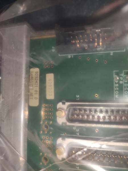
IS200BPVCG1BR1
The Real-World Problem It Solves
You know the frustration: a loose backplane connector causing intermittent contact resistance in a critical turbine control rack, or a bent pin in the VME slot taking down your entire Mark VI system during a vibration event. The IS200BPVCG1BR1 provides the physical backbone that keeps your control boards seated and communicating. It’s not glamorous—no processors, no firmware—but without this board, your UCVE processors and I/O cards have no home and no way to talk to each other. The 39 front-panel I/O connectors let you land field wiring via ribbon cables without disassembling the rack, saving hours during commissioning and maintenance.
Where you’ll typically find it:
-
259B2460BTG2 protection racks in Mark VI Speedtronic control cabinets for Frame 7/9 gas turbines
-
VME chassis in EX2100 excitation systems where multiple IS200-series boards need physical mounting
-
Retrofit projects upgrading Mark V to Mark VI where the backplane must be replaced to support new I/O
Bottom line: It’s the physical foundation of your Mark VI control system—passive, reliable, and absolutely critical for maintaining signal integrity between VME boards in vibrating, thermally cycling environments.
Hardware Architecture & Under-the-Hood Logic
The IS200BPVCG1BR1 is a passive backplane—no microprocessors, no power supplies, just copper traces and connectors. It mounts vertically in the 259B2460BTG2 rack, with the 21 VME slots arranged to accept standard 6U VME cards. The rear of the board has female DIN 41612 connectors (VME standard) that mate with the male connectors on your IS200VCMI, IS200ERSC, and other Mark VI boards. The front exposes 39 I/O headers (typically 34-pin or 50-pin ribbon cable connectors) that break out field signals to terminal boards.
Signal flow and interconnect logic:
-
VME Bus Distribution: Address, data, and control lines from the VME bus master (typically in Slot 1) route through the backplane to all 21 slots, allowing any board to access shared resources
-
I/O Signal Breakout: Field signals entering via the 39 front-panel ribbon cable connectors route to specific VME slots based on backplane wiring—each slot has dedicated I/O channels mapped to specific connectors
-
Power Distribution: +5V, ±12V from external power supplies (like IS200DCFBG1A) distribute through heavy copper planes on the backplane to all VME slots, with decoupling capacitors near each connector
-
Retention Mechanism: The rack borders physically lock boards into the backplane connectors, preventing vibration-induced fretting corrosion and contact resistance issues common in turbine control cabinets
-
Grounding: Dedicated ground planes and shielding on the backplane minimize EMI between high-speed digital VME signals and analog I/O lines

IS200BPVCG1BR1
Field Service Pitfalls: What Rookies Get Wrong
Treating This Like an Active Component Rookies see “ASM” (Assembly) in the name and think this is a programmable controller or power supply. It’s not. The IS200BPVCG1BR1 is a passive PCB with no firmware, no LEDs, no diagnostic capability. If your Mark VI system faults, swapping the backplane won’t fix software or processor issues—but it will fix intermittent contact problems caused by oxidation or bent pins.
Field Rule: Verify the backplane is truly at fault before replacement. Check for bent pins in the VME connectors using a flashlight and dental mirror. Measure continuity from the front I/O connectors to the expected VME slot pins with a multimeter. Only replace if you find open circuits, cracked traces, or severe connector damage.
Forgetting the Retention Border Alignment The 259B2460BTG2 rack has mechanical borders that guide boards into the backplane and lock them in place. Rookies remove the backplane for inspection and reinstall it without checking border alignment. Boards then don’t seat fully, causing intermittent contact resistance that looks like I/O failures or processor faults.
Quick Fix: When reinstalling the IS200BPVCG1BR1, verify the plastic retention borders are properly seated in the rack frame. The borders should align with the VME slot keying. Test-fit a known-good VME board (like a VCMI) in each slot—it should slide in smoothly and click into place. If you feel resistance, the backplane is misaligned and needs repositioning before you damage board connectors.
Ignoring Ribbon Cable Strain Relief The 39 front-panel I/O connectors accept ribbon cables that carry field signals. Rookies route these cables with sharp bends or without strain relief, causing the IDC (insulation displacement connector) contacts to work loose over time from vibration. Intermittent “field fault” alarms result.
Field Rule: Use proper ribbon cable routing with minimum 1-inch bend radius. Install cable ties to the rack frame to prevent vibration transfer from field wiring to the backplane connectors. Never pull on the ribbon cable to remove it—use the connector latch tabs. Check IDC connectors for proper seating; if the cable jacket isn’t fully inserted, the contacts will fail under vibration. Replace any ribbon cable that shows creasing or damage.


