
Description
Hard-Numbers: Technical Specifications
- Terminal Screw Torque: 5.0 lb-in (0.56 N-m) recommended torque setting.
- Wire Gauge Capacity: #18 AWG to #12 AWG (0.75 – 4.0 mm²).
- Operating Temperature: -20°C to +60°C.
- Maximum Voltage Rating: 300 VAC / 250 VDC.
- Wire Stripping Length: 7/16 inch (11 mm) required for proper insertion.
- Mounting Style: 35mm DIN Rail or Direct Panel Mounting.
- Dimensions (approx.): 200mm x 120mm x 32mm.
- Connection Interface: IDC (Insulation Displacement Connector) ribbon cables to I/O packs.
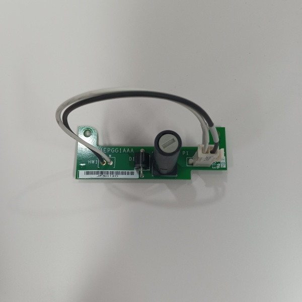
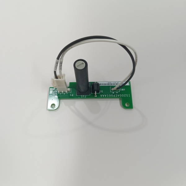
IS200AEPGG1A
The Real-World Problem It Solves
Inside a turbine control cabinet, you’re facing hundreds of field wires coming from pressure transmitters, temperature probes, and vibration sensors. Trying to land these directly onto the tiny, expensive pins of a Mark VI I/O card is a recipe for disaster. A slipped screwdriver or a momentary short can instantly fry a $5,000 module. This AEPG terminal board solves that headache. It mounts conveniently on a DIN rail, giving you spacious, rugged screw terminals to land your field wires. It then connects to the I/O card via a short ribbon cable, acting as a sacrificial buffer between the chaotic field world and your delicate electronics.
Where you’ll typically find it:
- Gas/Steam Turbine Control Cabinet Doors: Interfacing local panel-mounted instruments and field junction boxes to the core control modules.
- Balance of Plant (BOP) Skids: Connecting pumps, cooling fans, and local pressure switches in auxiliary systems.
- Retrofit Projects: Replacing archaic barrier terminal strips with a standardized, modular interface for Mark VIe upgrades.
It transforms a rat’s nest of field wiring into a clean, protected interface, drastically extending the lifespan of your pricey I/O hardware.
Hardware Architecture & Under-the-Hood Logic
This board does not contain a microprocessor or active logic. It is a passive, high-integrity signal router and wiring consolidation point. Its sole job is to provide a safe harbor for field wiring before handing off signals to the smart I/O packs.
- Field Signal Landing: 4-20mA loops, thermocouple leads, or RTD wires terminate at the sturdy screw-clamp terminals on the front of the board.
- Internal Trace Routing: Precision-etched PCB traces route these signals directly to the corresponding pins on the rear IDC connector block.
- Physical Isolation Barrier: The board maintains strict creepage distances and electrical clearances. It prevents high-voltage transients from the field side from arcing over and reaching the low-voltage I/O card plugged into the backplane.
IS200AEPGG1A
Field Service Pitfalls: What Rookies Get Wrong
Under-Torqued Terminals Causing Phantom Trips
A rookie uses a standard screwdriver to tighten the field wires. It feels tight, so he moves on. A month later, vibration from the turbine causes the screw to back off by a quarter-turn. The resulting intermittent open circuit triggers a false “Sensor Failure” alarm, costing the plant thousands in lost production while you chase ghosts.
- Field Rule: Always use a torque-limiting screwdriver set to the manufacturer’s spec (usually 5.0 lb-in). After torquing, give every wire a gentle tug to confirm it’s locked in place.
Using Undersized Wire Gauge (#22 AWG)
To save space in a cramped conduit, a junior engineer specifies #22 AWG wire for the 4-20mA loops landing on this board. The small surface area of the wire creates a high-resistance connection. Over time, heat builds up at the terminal, leading to oxidation, signal drift, and eventually a melted plastic housing.
- Quick Fix: Adhere strictly to the #18 AWG minimum wire gauge requirement. If you need flexibility, use finely stranded #18 AWG wire with a ferrule crimp. Never compromise on conductor size for the sake of saving a few millimeters of space.
Mixing High-Speed Digital and Low-Level Analog Signals
A rookie lands the 120VAC starter coil feedback for a lube oil pump (high di/dt, noisy) right next to the millivolt-level thermocouple inputs on the same AEPG board. Electromagnetic interference (EMI) from the coil induces noise into the TC circuit, causing the exhaust temperature spread to fluctuate wildly and forcing the turbine into a load limit.
- Field Rule: Physically segregate your signals. Keep analog inputs (TC, RTD, 4-20mA) on dedicated terminal boards. If you must mix them on one board, leave at least three empty terminal positions (a physical isolation gap) between high-power digital circuits and sensitive analog measurements.
Commercial Availability & Pricing Note
Please note: The listed price is for reference only and is not binding. Final pricing and terms are subject to negotiation based on current market conditions and availability.


