
Description
Hard-Numbers: Technical Specifications
- Supply Voltage: 24 VDC (typical industrial range).
- Operating Temperature: -20°C to +60°C.
- Dimensions (approx.): 110 mm × 240 mm.
- Weight (approx.): ~0.22 kg.
- Mounting Pattern: Factory-drilled holes (corner and edge locations).
- Connectivity: Vertical pin connectors for backplane and peripheral interfacing.
- Signal Processing: Analog and Digital I/O capabilities (varies by specific application).
- Mechanical Form Factor: PCB assembly without a faceplate, mounted directly to the rack chassis.
The Real-World Problem It Solves
When you’re knee-deep in a turbine control cabinet, you don’t have time for flimsy, jury-rigged interfaces that vibrate loose or pick up massive amounts of electrical noise. This AEPC board provides a stable, grounded platform to process auxiliary signals and interface with the core controller. It eliminates the need for external marshalling panels and keeps your critical analog and digital data clean.
Where you’ll typically find it:
- Gas/Steam Turbine Auxiliary Panels: Processing signals from lube oil coolers, seal oil systems, or ventilation fans.
- Wind Turbine Nacelle Controls: Interfacing with yaw motors, nacelle cooling systems, and emergency stop loops.
- Retrofit and Upgrade Projects: Replacing discontinued third-party interface cards with a GE-standard solution.
It’s the unsung hero that keeps the “small stuff” running reliably so the main turbine control loop can do its job without interruption.
Hardware Architecture & Under-the-Hood Logic
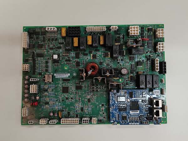
This isn’t a standalone computer; it’s a purpose-built circuit assembly living inside a larger Mark VI ecosystem. It relies on the main controller for intelligence but handles the dirty work of signal conditioning.
- Chassis Grounding & Mechanical Stability: The defining feature is the conductive material surrounding the drilled mounting holes. When secured to the metal rack frame, this creates a low-impedance ground path, drastically improving EMI/RFI rejection and preventing the PCB from cracking under turbine-induced vibrations.
- Signal Buffering & Conditioning: Raw signals from field devices (like 4-20mA transmitters or 24VDC proximity switches) enter the board. Internal resistors, capacitors, and buffer amplifiers condition these signals, scaling them appropriately and filtering out electrical hash before passing them to the main processor.
- Inter-board Communication: Vertical pin connectors on the PCB establish a physical link to the Mark VI backplane or other adjacent boards. It acts as a translator, taking processed field data and formatting it into the data packets the main controller expects.
Field Service Pitfalls: What Rookies Get Wrong
Using Nylon Standoffs Instead of Conductive Hardware
New techs see the mounting holes and instinctively reach for the plastic nylon standoffs lying around the shop. They screw the board in, and it feels solid. Three months later, the turbine is throwing random “Sensor Fault” alarms during high-vibration events because the board has no chassis ground.
- Field Rule: Always use metallic standoffs and screws when mounting AEPC family boards. Ensure there is solid metal-on-metal contact between the screw head/washer and the conductive ring around the hole. Torque them down firmly.
Forcing a Mismatched Revision into an Existing Rack
You have a dead IS200AEPCH1 on hand and a brand new IS200AEPCH1A sitting on the shelf. You swap them because “a board is a board.” The system powers up, but the diagnostic LED blinks a code you’ve never seen, and the controller refuses to talk to the card.
- Quick Fix: Never assume hardware revisions are plug-and-play. Check the full part number on the failed unit. If the revision codes (the letters after the numbers) don’t match, you may need to update the controller’s firmware or request a specific older revision from the supplier.
Chasing Ghost Faults Due to Poor Wire Management
An engineer crams 20 unlabeled wires into the terminal strip connected to this board. Six months later, a vibration-induced wire chafes against the sharp edge of the neighboring terminal block. It intermittently shorts to ground, causing the turbine to trip on a false “Low Lube Oil Pressure” alarm.
- Field Rule: Use labeled, heat-shrink tubing on every wire connected to this PCB. Route wires neatly using DIN-rail mounted cable duct or zip-ties. Ensure no bare conductors are exposed and that wires cannot rub against sharp metal edges inside the cabinet.
Please note: The listed price is for reference only and is not binding. Final pricing and terms are subject to negotiation based on current market conditions and availability.


