
Description
Hard-Numbers: Technical Specifications
- Supply Voltage: 24 VDC (internal regulation)
- Operating Temperature: -40°C to +70°C (extended industrial range)
- Analog I/O: 8 analog inputs, 1 analog output
- Encoder Inputs: 1 incremental encoder, 1 absolute encoder
- Discrete I/O: 20 discrete inputs, 1 discrete output
- Relay Outputs: 8 onboard relays, 12 general relays
- Brake Control: 1 dedicated brake control output
- Communication Ports: 2 RS-485 interfaces
- Surge Protection: 6 MOVs (metal-oxide varistors)
- Connectivity: 2 male pin connectors (processor interface), 17 vertical female pin connectors (2-20 pins)
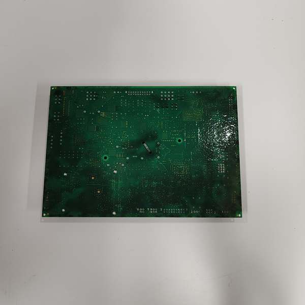
- Mechanical Housing: HW1-marked C-shaped metal housing
GE IS200AEPAH1BKE
The Real-World Problem It Solves
Wind turbine nacelles are brutal environments. Salt spray and 100mph winds eat standard PCBs, while vibration cracks solder joints and lightning fries unprotected traces. You need a board that won’t rot out or shake apart. This AEPA variant is built for the job, handling the dirty business of pitch motors and encoders while the Mark VIe controller stays clean in its protected cabinet.
Where you’ll typically find it:
- Offshore Wind Farms: Battling 100% humidity and salt fog in nacelles miles from shore.
- Onshore Turbines: In utility-scale arrays where lightning strikes are a weekly occurrence.
- Retrofit Projects: Upgrading older Mark VI systems with hardware designed to survive the elements.
It turns a hostile environment into just another Tuesday for your control system.
Hardware Architecture & Under-the-Hood Logic
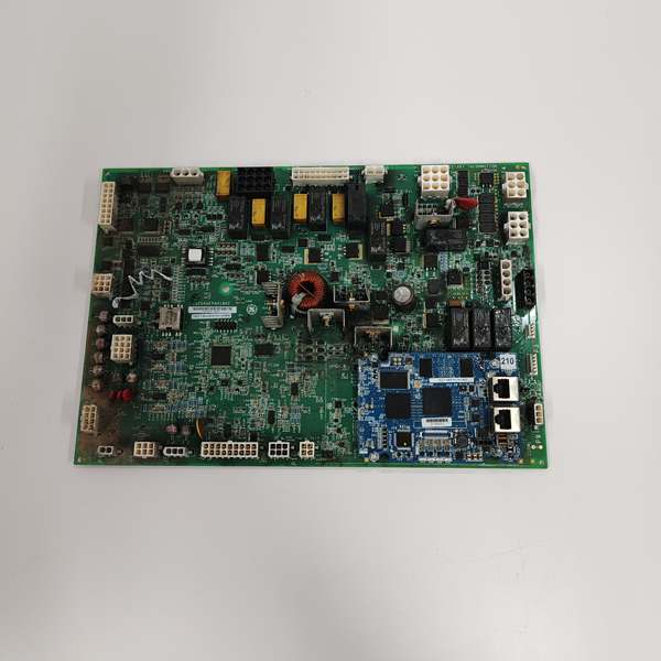
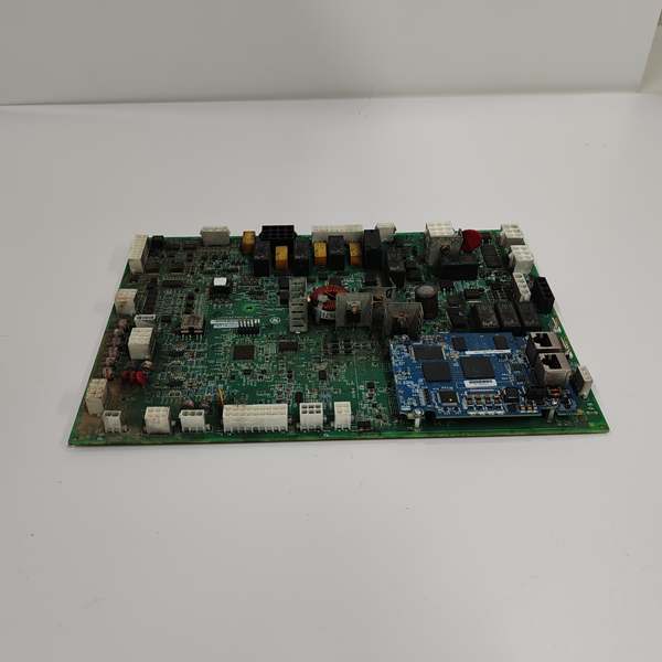
This isn’t a passive daughter card. It’s a localized signal processing hub designed to take the mechanical and electrical abuse that would destroy a standard I/O module. The “BKE” suffix indicates a specific bill of materials with higher-grade passives.
- Processor Interface (The Data Highway): Two robust male pin connectors in the upper-left corner link directly to the Mark VIe processor. This creates a dedicated, high-speed path that keeps pitch setpoints away from the noisy sensor world.
- Feedback Conditioning (The Noise Filter): Nearby 500kW pitch motors dump massive electrical hash into the system. The onboard amplifiers scrub sine/cosine pulses from the absolute and incremental encoders before passing clean position data to the processor. This prevents false overspeed trips.
- Actuator Drive Logic (The Muscle): Eight relay outputs and one discrete output are the heavy lifters. On command, they energize coils that engage hydraulic solenoid valves or electric motor contactors to turn the blades. The dedicated brake output feathers the blades if the processor watchdog times out.
- Environmental Armor (The Defense): Six MOVs clamp voltage spikes from nearby lightning strikes. The conformal coating prevents moisture ingress. The C-shaped HW1 metal housing acts as a Faraday cage, blocking EMI from the pitch drives.
GE IS200AEPAH1BKE
Field Service Pitfalls: What Rookies Get Wrong
Burning Out Encoders by Ignoring the Supply Jumper
A rookie wires a brand-new 24VDC absolute encoder, assuming the board’s power supply is universal. The JP1 jumper near the encoder connectors is set to 5VDC by default. The encoder fries instantly.
- Field Rule: Locate the JP1 jumper block before energizing the system. Set it explicitly for 5V or 24V to match your field device. Always verify the output voltage with a multimeter at the connector pins before plugging in the sensor.
Tossing the C-Shaped Metal Housing (HW1)
A technician removes the board for troubleshooting and tosses the unique C-shaped metal housing (marked HW1) aside to get better access to the pins. They reinstall the naked PCB. Within a month, vibration from the gearbox cracks the board around the pin connectors, causing an intermittent fault that takes days to trace.
- Quick Fix: Treat the HW1 housing as a critical component. Always reinstall it using the factory standoff screws. It’s the EMI shield and structural backbone of the assembly. If you lose it, order a replacement immediately. Do not operate the turbine without it.
Chasing Ghost Faults from Failed MOVs
A lightning storm rolls through, causing a momentary comms glitch. The turbine keeps running, so the rookie shrugs it off. They don’t know that one of the six MOVs has failed short-circuited. Two weeks later, a second strike hits, the shorted MOV creates a dead short, blows the 24VDC fuse, and causes a full turbine trip.
- Field Rule: After any significant electrical storm, perform a visual and multimeter inspection of the six MOVs. A healthy MOV reads in the megaohms. A failed one reads near zero ohms. If you find even one compromised MOV, replace the entire board. The others are living on borrowed time.
Please note: The listed price is for reference only and is not binding. Final pricing and terms are subject to negotiation based on current market conditions and availability.


