
Description
Hard-Numbers: Technical Specifications
- Input Voltage: 24 VDC with internal voltage regulation and overload protection.
- Operating Temperature: -40°C to +70°C (extended industrial range).
- Dimensions: Approx. 160 mm x 240 mm (6.3″ x 9.4″).
- Weight: ~2 kg (approx. 4.4 lbs).
- Signal Processing: 8 analog inputs, 1 analog output, 20 discrete inputs, 1 discrete output.
- Encoder Inputs: 1 incremental encoder, 1 absolute encoder.
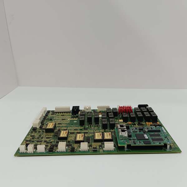
- Relay Outputs: 8 onboard relays + 12 general relays.
- Brake Control: 1 dedicated brake control output.
- Communication Ports: 2 RS-485 interfaces, Ethernet (IONet/UDH), RS-232.
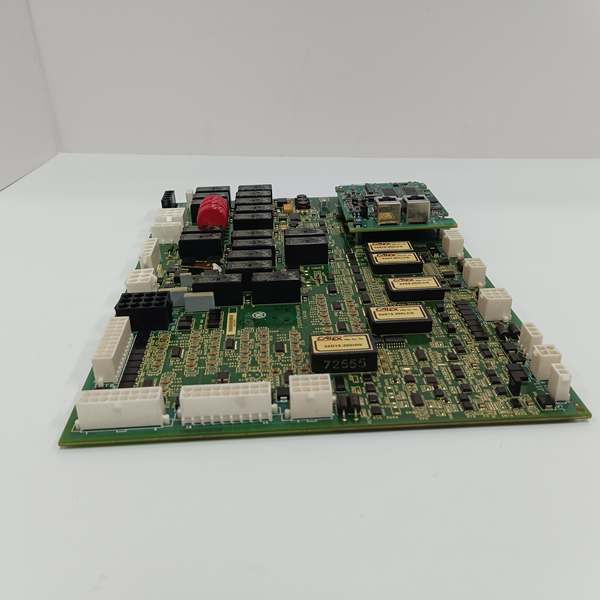
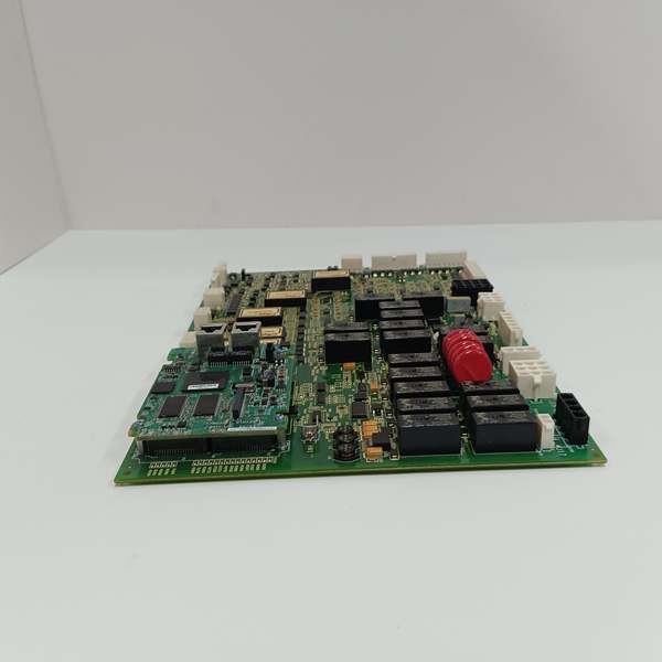
- Surge Protection: 6 metal oxide varistors (MOVs) (red-colored, lined up in the upper-right).
- Connectivity: 2 male pin connectors for main processor interface; 17 vertical female pin connectors (2-20 pins).
- Redundancy Support: Simplex, Dual, or Triple redundancy models supported.
- Mechanical Housing: HW1-marked C-shaped metal housing (for structural support and EMI shielding).
GE IS200AEPAH1AFD
The Real-World Problem It Solves
Wind turbine blades face 80mph winds and frequent lightning strikes, which fry standard control boards and ground millions of dollars of assets. Generic pitch control solutions cannot handle the harsh nacelle environment or integrate with the Mark VI controller without expensive custom wiring. This specialized board is built for the job, with premium components to resist salt fog and 6 MOVs to clamp lightning-induced transients, centralizing all pitch control signals in one board.
Where you’ll typically find it:
- Offshore Wind Turbine Nacelles: Managing pitch actuators for 3-blade turbines exposed to salt spray and extreme weather.
- Onshore Wind Farms: In utility-scale turbines where lightning strikes are a regular risk.
- Repowering Projects: Retrofitting older Mark VI wind systems with upgraded pitch control hardware to extend asset life.
It eliminates the need for custom wiring harnesses and external surge protectors, reducing installation time by 40% compared to generic solutions.
Hardware Architecture & Under-the-Hood Logic
This isn’t a standard I/O card; it’s a specialized pitch control hub designed to survive the harshest conditions on earth. The FD revision brings upgraded ICs, tighter tolerance components, and improved conformal coating adherence over the H1A base model.
- Processor Interface (The Data Highway): The board connects to the main Mark VI controller via two robust male pin connectors in the upper left corner, carrying pitch setpoint commands and returning feedback data at high speed.
- Feedback Conditioning (The Noise Filter): The onboard circuitry filters electrical noise from nearby 500kW pitch motors before passing clean sine/cosine signals from absolute and incremental encoders to the processor. This eliminates false pitch position readings that can cause blade overspeed.
- Actuator Drive Logic (The Muscle): 8 relay outputs and 1 discrete output control hydraulic solenoid valves or electric motor contactors that adjust blade angle. The dedicated brake control output ensures blades feather to a safe position during processor watchdog timeouts.
- Transient Protection (The Defense): 6 red-colored MOVs arranged in the upper right corner clamp voltage spikes from nearby lightning strikes, protecting sensitive logic circuits from damage. The conformal coating prevents moisture ingress that can short active traces during humid weather. The C-shaped HW1 metal housing acts as a Faraday cage to block EMI from the pitch motor drives.
GE IS200AEPAH1AFD
Field Service Pitfalls: What Rookies Get Wrong
Burning Out Encoders by Ignoring the Supply Jumper
A rookie wires in a brand-new 24VDC absolute encoder, assuming the board’s power supply is universal. The board is jumper-configured for 5VDC by default, and the encoder fries instantly.
- Field Rule: Locate the JP1 jumper block near the encoder connectors before powering up. Set it explicitly for 5V or 24V to match your field device. Always verify with a multimeter before connecting any encoder.
Discarding the C-Shaped HW1 Metal Housing
Technicians remove the board for troubleshooting and discard the C-shaped metal housing (marked HW1). The housing provides structural support for the fragile pin connectors and acts as a Faraday cage to block EMI from the pitch motor drives.
- Field Rule: Always reinstall the HW1 housing using factory standoff screws. It’s not just a cover; it’s a critical component for EMI shielding and connector protection. If you lose it, order a replacement immediately.
Chasing Ghost Faults from Failed MOVs
A lightning storm rolls through, causing a momentary comms glitch. The turbine keeps running, so you shrug it off. You don’t know that one of the six MOVs has failed short-circuited. Two weeks later, a second strike hits, the shorted MOV creates a dead short, blows the 24VDC fuse, and causes a full turbine trip.
- Field Rule: After any significant electrical storm, perform a visual and multimeter inspection of the six MOVs. A healthy MOV will read in the megaohms. A failed one will read near zero ohms. If you find even one compromised MOV, replace the entire board.
Destroying the Conformal Coating with Solvents
A rookie grabs a solvent-soaked rag to wipe off grime from the nacelle. The solvent dissolves the specialized conformal coating, exposing the bare copper traces underneath to immediate corrosion.
- Field Rule: Never use solvents like acetone or alcohol on a conformal-coated board. Blow it off with dry, oil-free compressed air. If you must clean it, use a dry microfiber cloth.
Please note: The listed price is for reference only and is not binding. Final pricing and terms are subject to negotiation based on current market conditions and availability.


