
Description
Hard-Numbers: Technical Specifications
- Analog I/O: 8 analog inputs, 1 analog output .
- Encoder Inputs: 1 incremental encoder, 1 absolute encoder .
- Discrete I/O: 20 discrete inputs, 1 discrete output .
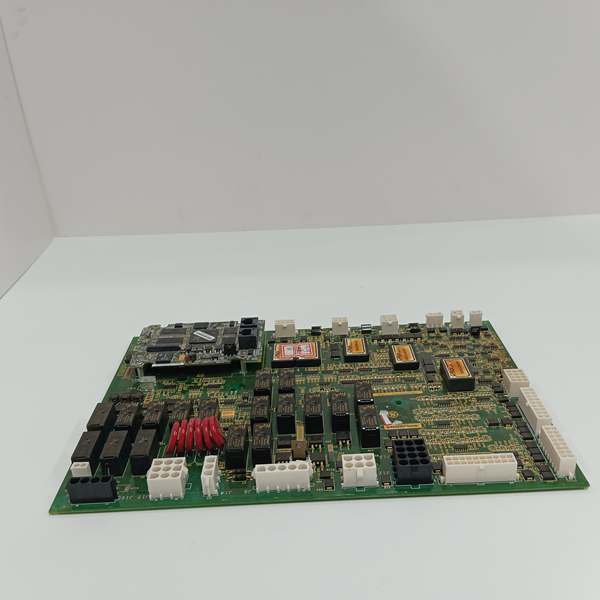
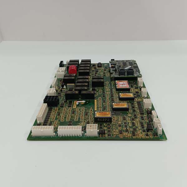
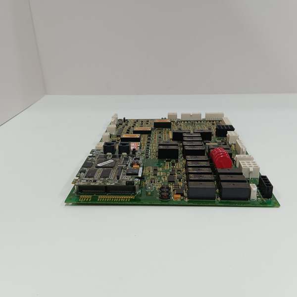
- Relay Outputs: 8 onboard relays + 12 general relays .
- Brake Control: 1 dedicated brake control output .
- Communication Ports: 2 RS-485 interfaces .
- Surge Protection: 6 metal oxide varistors (MOVs) .
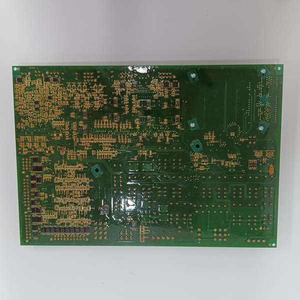
- Connectivity: 17 vertical female pin connectors (2-20 pins); 2 male pin connectors for processor interface .
- Status Indicators: 2 operational LEDs on left edge .
- Mechanical Housing: HW1-marked C-shaped metal housing (structural/EMI protection) .
- Weight: 0.68 kg .
GE IS200AEPAH1ACB
The Real-World Problem It Solves
You need a single, bulletproof interface to bridge the gap between the Mark VIe controller and the violent, high-voltage world of pitch motors and encoders. Plugging these noisy, high-current devices directly into the main controller would fry the backplane and cause endless ground loops. This board acts as the rugged bouncer. It buffers the signals, clamps the lightning-induced transients with MOVs, and ensures the controller only sees clean data.
Where you’ll typically find it:
- Wind Turbine Nacelles: Directly interfacing with blade pitch hydraulic power units or electric servos to catch variable winds.
- Encoder Feedback Loops: Reading absolute and incremental encoders to provide closed-loop control of blade angles.
- Emergency Pitch Systems: Driving the dedicated brake control output and monitoring E-Stop pushbuttons for feathering blades during overspeed events.
It eliminates the need for external signal conditioners and standalone surge protectors in the turbine nacelle.
Hardware Architecture & Under-the-Hood Logic
This isn’t a passive daughter card; it’s a localized signal processing hub built to survive the mechanical abuse of a spinning nacelle. The “CB” revision brings refined componentry and robust assembly over the base H1A model.
- Processor Interface & Data Highway: The module talks to the main Mark VIe processor via two robust male pin connectors in the upper left corner, forming a high-speed data link independent of the primary IONet .
- Feedback Filtering & Conditioning: The onboard circuits scrub the electrical hash generated by nearby 480V pitch motor drives. They condition the sine/cosine pulses from absolute/incremental encoders before sending clean position and speed data to the processor .
- Actuator Drive Logic: The 8 onboard relays and 1 discrete output are the muscle. Upon receiving a setpoint command, they energize the coils that engage the hydraulic solenoid valves or electric motor contactors controlling blade pitch .
- Transient Clamping & Structural Rigidity: The line of 6 MOVs clamps any voltage spikes from nearby lightning strikes, protecting the logic circuits. The unique HW1-marked C-shaped metal housing provides structural rigidity for the fragile pin connectors and acts as a Faraday cage to block EMI .
GE IS200AEPAH1ACB
Field Service Pitfalls: What Rookies Get Wrong
Mismatching Encoder Supply Voltages
A rookie wires in a brand-new absolute encoder that runs on 24VDC, assuming the AEPA board’s encoder supply is universal. The encoder burns out instantly because the board is jumper-configured for 5VDC.
- Field Rule: Check the encoder supply jumper on the PCB before powering up. Locate the JP1 or similar jumper block near the encoder connectors. Set it explicitly for 5V or 24V to match your field device. Never assume.
Ignoring the C-Shaped Metal Housing (HW1)
Technicians remove the board for troubleshooting and carelessly toss it onto a conductive workbench, or fail to remount the unique C-shaped metal housing (marked HW1) that came with the board. This leaves the PCB vulnerable to physical damage and EMI .
- Quick Fix: Always reinstall the C-shaped metal housing (HW1) using the factory standoff screws. This isn’t just a cosmetic cover; it’s part of the board’s electromagnetic shielding and structural rigidity. Treat it as a critical component.
Cascading Failures from MOVs
One of the 6 metal-oxide varistors (MOVs) fails short-circuited during a lightning strike. A rookie just replaces the fuse and powers the system back up. The shorted MOV immediately blows the new fuse, and the rookie blames the power supply.
- Field Rule: Visually inspect the 6 MOVs (located in a single line on the PCB) for cracking or discoloration. Use a multimeter to check resistance across each MOV. A healthy MOV reads megaohms; a blown one reads near zero. Replace the entire board if multiple MOVs are compromised.
Please note: The listed price is for reference only and is not binding. Final pricing and terms are subject to negotiation based on current market conditions and availability.


