
Description
Hard-Numbers: Technical Specifications
- Supply Voltage: 24 VDC (typical industrial)
- Operating Temperature: -20°C to +60°C
- Dimensions (approx.): 110 mm × 240 mm
- Weight (approx.): ~0.22 kg
- I/O Capability: Analog input/output functions for turbine control/monitoring (specific channel counts and ranges depend on revision/configuration)
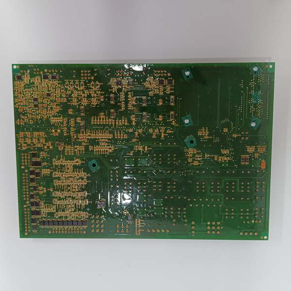
- Mounting: Factory-drilled holes (corners + internal/edge) with conductive material surround for grounded mounting
- Comms/Integration: Positioned within Mark VI control/monitoring architecture; exact comms details vary by revision
- Mechanical Form Factor: PCB assembly, typically installed in control cabinet framework/rack arrangement per Mark VI practice
GE IS200AEPAH1ABC
The Real-World Problem It Solves
Turbine control cabinets get crowded fast. You need a reliable way to mount, ground, and wire key control/monitoring cards without jury-rigging brackets or relying on flimsy standoffs. This PCB’s factory-drilled, conductively framed mounting scheme gives you repeatable installs and better EMI grounding discipline.
Where you’ll typically find it:
- Mark VI turbine control cabinets doing control/monitoring roles (gas/steam/auxiliaries)
- Retrofit/replacement work where you’re swapping AEPA-family boards to restore I/O or diagnostics
- Cabinets where clean grounding and consistent mounting are non-negotiable (vibration, heat, life-safety)
It’s not “exciting hardware.” It’s the kind of part that keeps your system from drifting into intermittent faults caused by poor mounting and grounding.
Hardware Architecture & Under-the-Hood Logic
Think of this as a Mark VI control/monitoring building block—not a standalone computer, but a board that lives inside a larger system and talks to the rest of the rack via connectors and backplane paths.
- Mounting & Grounding Backbone: Conductive material around the drilled holes ties the PCB mechanically and electrically to the chassis/frame, improving EMI performance and repeatability of installs .
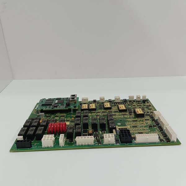
- Signal I/O Path: Analog/digital interfaces bring field/process variables into the system and/or drive outputs that influence control behavior (exact channels/ranges vary by revision) .
- Processing & Conditioning: Typical Mark VI PCBs include ICs (FPGAs/processors), signal conditioning, and filtering to make raw sensors usable and robust .
- Diagnostics Presence: Like other AEPA-family boards, it tends to expose status/fault indicators and participates in the system’s diagnostic picture (exact LED behavior depends on firmware/revision) .
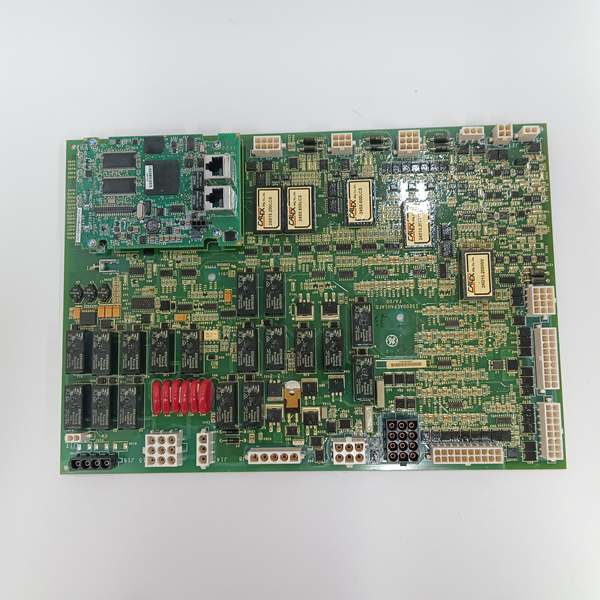
GE IS200AEPAH1ABC
Field Service Pitfalls: What Rookies Get Wrong
Assuming “ABC” Revision Works Exactly Like “A” or “ACB”
Older spares may fit mechanically but behave differently electrically or firmware-wise. You can end up chasing ghost faults because the system expects a different revision’s behavior.
- Quick Fix: Verify the full label P/N (including revision) and match it unless you have written cross-compatibility from the OEM docs/cabinet drawing set.
Mismounting and Ignoring Conductive Hole Material
If you mount with nylon standoffs and ignore the conductive surround, you lose the intended grounding path and invite noise or intermittent contact.
- Field Rule: Use metal standoffs/hardware where indicated and confirm chassis continuity with a meter; verify mounting torque is firm but not stripped.
Wiring Without Checking the Exact Pinout/Assignment
AEPA-family boards can differ in pin assignments across revisions. Rookies copy an old drawing and land wires incorrectly, then blame the card.
- Quick Fix: Pull the current drawing/schematic for your exact revision and confirm terminal assignments before energizing anything.
Commercial Availability & Pricing Note
Please note: The listed price is for reference only and is not binding. Final pricing and terms are subject to negotiation based on current market conditions and availability.


