
Description
Hard-Numbers: Technical Specifications
- Power Input: 24 VDC with internal voltage regulation and overload protection.
- Signal Processing: Analog and Digital I/O integration (supports temperature, pressure, speed transducers).
- Communication Ports: Ethernet and High-Speed Serial interfaces.
- Operating Temperature: -40°C to +70°C (-40°F to +158°F).
- Relative Humidity: 5% to 95%, non-condensing.
- Protection Rating: IP20 (requires enclosure); includes surge protection (Varistors).
- Mounting: Standard 19-inch rack mount or Mark VIe backplane compatible.
- Hot-Swap: Supported (reduces unplanned downtime).
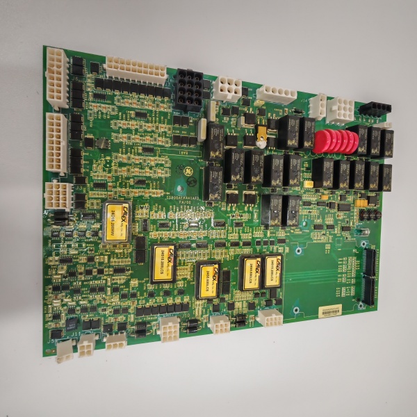
GE IS200AEPAH1ABB
The Real-World Problem It Solves
You’ve got a Mark VIe rack stuffed with specialized cards, but you still need a centralized hub to distribute clean 24VDC, condition raw sensor signals, and provide a hardware-level watchdog for the system. This board kills the need for external power conditioners and messy terminal strips by integrating power management, ADCs, relays, and serial comms onto a single, hardened PCB.
Where you’ll typically find it:
- Gas & Steam Turbine Skids: Distributing regulated power to proximity probes, LVDTs, and pressure transmitters while feeding conditioned signals back to the main controller.
- Wind Turbine Nacelle Auxiliaries: Managing yaw motors, cooling fans, and emergency stop loops in harsh, vibration-heavy environments.
- Retrofit Projects: Replacing obsolete relay logic and standalone signal conditioners in aging power generation facilities.
It consolidates power distribution, signal isolation, and basic protection into one bulletproof module.
Hardware Architecture & Under-the-Hood Logic
This isn’t a passive backplane extender; it’s a localized power and signal management node. Unlike the H1A/H1AAA variants focused strictly on blade pitch axes, the -ABB is a general-purpose workhorse for broader turbine auxiliaries.
- Power Regulation & Distribution: The 24VDC input passes through onboard regulators and filtering circuits. It provides clean, stabilized power to downstream I/O devices and protects the rack from voltage sags or spikes .
- Signal Conditioning & Processing: Raw analog signals (e.g., 4-20mA from a pressure transducer) are routed through precision resistor strings and buffer amps. The onboard logic scales these values, eliminating the need for external marshalling panels .
- Centralized Interfacing: It aggregates discrete inputs (emergency stops, limit switches) and controls relay outputs (alarms, solenoid valves). It acts as a firewall, preventing inductive kickback from field devices from reaching the delicate main processor .
- Communication Bridge: High-speed serial and Ethernet ports facilitate rapid data exchange with the Mark VIe backplane, ensuring that auxiliary system statuses (oil pressure low, filter clogged) are polled without bogging down the primary control loop.
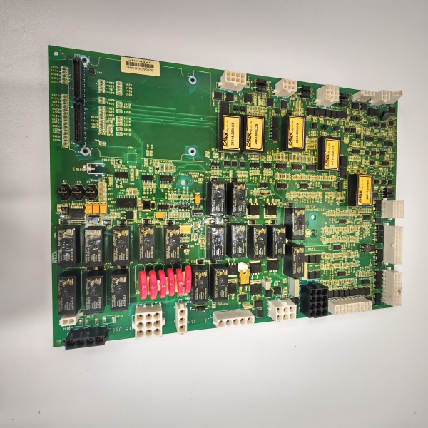
GE IS200AEPAH1ABB
Field Service Pitfalls: What Rookies Get Wrong
Overlooking Power Supply Polarity During Commissioning
A rookie rushes the wiring, connects the 24VDC supply backwards to the auxiliary board, and wonders why the entire I/O rack doesn’t power up or immediately trips a breaker. The onboard reverse polarity protection might save the board, but it will absolutely kill the power to your sensors.
- Field Rule: Always use a multimeter to verify polarity at the terminal block before tightening the lug. Confirm +24VDC on the positive rail and 0VDC on the negative. If the LED indicators don’t flash during the initial power-up sequence, check your fuses first.
Using Unshielded Cable for Analog Sensors
You wire a critical vibration probe or LVDT position sensor using standard zip cord because it was the nearest spool. Electrical noise from nearby 480V motor starters induces phantom signals, causing the turbine to trip on “False Overspeed” or erratic valve hunting.
- Quick Fix: Use shielded, twisted-pair (STP) cable for all analog inputs. Terminate the drain wire to the chassis ground at the AEPA board end only. Keep analog and digital signal wires separated by at least 6 inches (150mm) in the conduit.
Ignoring the Redundant Power Feed Option
The board supports redundant power inputs, but a rookie only lands one 24VDC feed because “one is enough.” When that single power supply fails during a storm or maintenance window, the auxiliary systems go dark, triggering a turbine trip.
- Field Rule: If your facility has redundant DC power supplies, use them. Land the primary supply on the main terminals and the backup on the designated redundant terminals. The board will seamlessly switch between them without dropping the signal to the controller.
Please note: The listed price is for reference only and is not binding. Final pricing and terms are subject to negotiation based on current market conditions and availability.


