
Description
Hard-Numbers: Technical Specifications
- Analog I/O: 8 analog inputs, 1 analog output .
- Encoder Inputs: 1 incremental encoder, 1 absolute encoder .
- Discrete I/O: 20 discrete inputs, 1 discrete output .
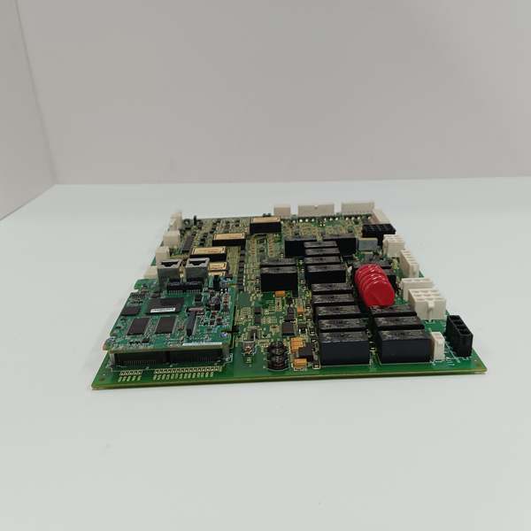
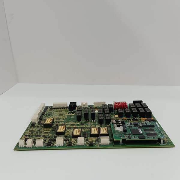
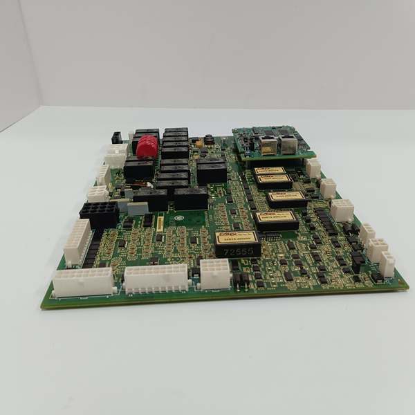
- Relay Outputs: 8 relay outputs (plus an additional 12 general relays on the PCB) .
- Brake Control: 1 dedicated brake control output .
- Communication Ports: 2 RS-485 interfaces .
- Surge Protection: 6 metal-oxide varistors (MOVs) arranged in a single line .
- Connectivity: Communicates with the main processor via 2 male pin connectors in the upper-left corner .
- Operating Temperature: 0°C to +60°C (standard industrial range) .
- Mounting: Requires a dedicated mounting base for secure installation .
- Status Indicators: 2 LED indicators located along the left edge of the base board .
GE IS200AEPAH1A
The Real-World Problem It Solves
Wind turbine blades need precise, lightning-fast angular adjustments to catch variable winds or feather during storms. Trying to run these high-current pitch motors and process noisy encoder feedback through a standard general-purpose I/O rack invites ground loops, electrical noise, and catastrophic blade overspeed. This dedicated board centralizes the chaos, providing a rugged, isolated interface that talks directly to the Mark VIe controller.
Where you’ll typically find it:
- Wind Turbine Nacelles: Bolted to the control cabinet, directly interfacing with the blade pitch hydraulic power units or electric servomotors.
- Pitch Bearing Monitoring: Reading absolute encoders (for blade position) and incremental encoders (for rotational speed) to provide closed-loop control to the Mark VIe.
- Emergency Stop Systems: Driving the dedicated brake control output and monitoring emergency stop pushbuttons and safety interlocks.
It turns a violent, high-energy mechanical system into a precisely controlled variable resistor for the wind.
Hardware Architecture & Under-the-Hood Logic
This isn’t a passive patch panel; it’s a localized signal conditioning and execution hub. It sits on the edge of the high-voltage pitch drive world and the low-voltage digital world of the Mark VIe controller.
- Processor Interface: The module communicates with the main Mark VIe processor board via two robust male pin connectors located in the upper-left corner, forming a high-speed data highway independent of the primary IONet backplane .
- Feedback Acquisition: The onboard circuits condition the sine/cosine or digital pulse trains coming from the absolute and incremental encoders. They filter out the electrical hash generated by nearby Variable Frequency Drives (VFDs) before passing clean position and speed data to the processor .
- Actuator Drive Logic: The 8 relay outputs and the single discrete output are the muscle. Upon receiving a command word from the processor, the board energizes the coils that engage the pitch hydraulic solenoid valves or electric motor contactors .
- Surge Suppression & Safety: The line of 6 metal-oxide varistors (MOVs) clamp any transient voltage spikes—common in lightning-prone wind farms—protecting the delicate logic circuits. The dedicated brake control output ensures that in a processor watchdog timeout or power loss, the blades default to a safe, feathered position .
GE IS200AEPAH1A
Field Service Pitfalls: What Rookies Get Wrong
Mismatching Encoder Supply Voltages
A rookie wires in a brand-new absolute encoder that runs on 24VDC, assuming the AEPA board’s encoder supply is universal. The encoder burns out instantly because the board is jumper-configured for 5VDC.
- Field Rule: Check the encoder supply jumper on the PCB before powering up. Locate the JP1 or similar jumper block near the encoder connectors. Set it explicitly for 5V or 24V to match your field device. Never assume.
Ignoring the C-Shaped Metal Housing (HW1)
Technicians remove the board for troubleshooting and carelessly toss it onto a conductive workbench, or fail to remount the unique C-shaped metal housing (marked HW1) that came with the board. This leaves the PCB vulnerable to physical damage and EMI .
- Quick Fix: Always reinstall the C-shaped metal housing (HW1) using the factory standoff screws. This isn’t just a cosmetic cover; it’s part of the board’s electromagnetic shielding and structural rigidity. Treat it as a critical component.
Cascading Failures from MOVs
One of the 6 metal-oxide varistors (MOVs) fails short-circuited during a lightning strike. A rookie just replaces the fuse and powers the system back up. The shorted MOV immediately blows the new fuse, and the rookie blames the power supply.
- Field Rule: Visually inspect the 6 MOVs (located in a single line on the PCB) for cracking or discoloration. Use a multimeter to check resistance across each MOV. A healthy MOV reads megaohms; a blown one reads near zero. Replace the entire board if multiple MOVs are compromised.
Please note: The listed price is for reference only and is not binding. Final pricing and terms are subject to negotiation based on current market conditions and availability.


