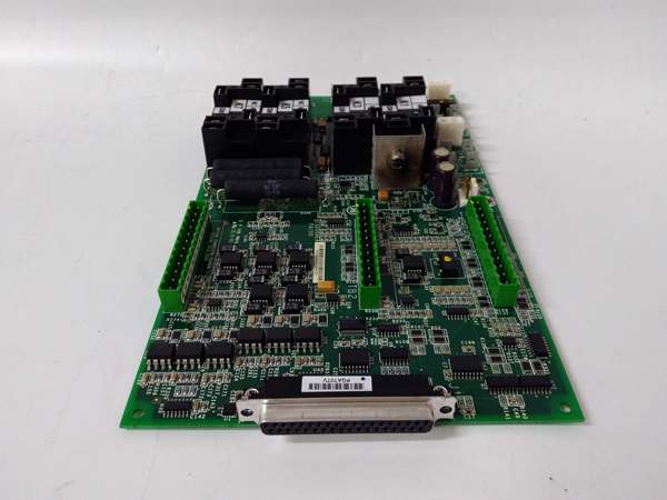
Description
System Architecture & Operational Principle
In the GE Mark VIe turbine control topology, the sits at the physical interface layer, directly connecting to the generator excitation system. Unlike a standard general-purpose I/O card, this is a specialized auxiliary interface board designed specifically for the harsh electrical environment of turbine excitation control.
The module’s primary job is to take raw, often noisy analog and discrete signals from exciter sensors and condition them into clean, isolated digital data for the Mark VIe processor. It features robust electrical isolation to prevent high-voltage transients from the exciter field from frying the sensitive logic processors. By handling signal filtering (both hardware and software-based) right at the terminal board, it ensures the turbine control algorithms receive highly accurate, low-latency feedback, which is absolutely vital for maintaining grid stability and preventing catastrophic turbine overspeed events.
Core Technical Specifications
- Module Function: Exciter Auxiliary Interface / Input Terminal Board
- System Compatibility: GE Mark VIe Control System, compatible with GE Fanuc 90-70 PLC series
- Power Requirement: 24VDC isolated power supply
- Operating Temperature: -10°C to +55°C (industrial standard); some variants rated -40°C to +85°C
- Relay Channels: 8 to 12 relay channels for signal isolation and power switching
- Analog I/O: Supports -10V to +10V analog input and 0 to +10V analog output
- Noise Suppression: Integrated hardware filters (500 rad/s single-pole) and configurable software low-pass filters
- Mounting: Modular plug-in rack / DIN rail mounting
- Protection Rating: Industrial standard IP20 (some variants up to IP67)
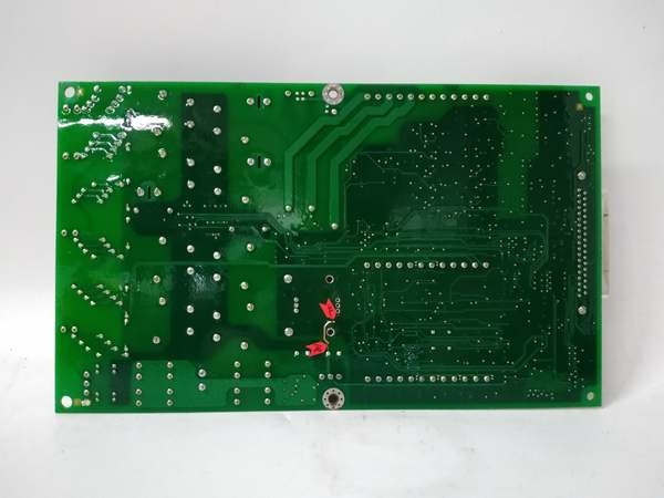
IS200AEADH4ADA
Customer Value & Operational Benefits
Unmatched Excitation System Stability
Exciter systems generate massive amounts of electrical noise. The ‘s built-in dual-stage hardware filtering and electrical isolation mean your turbine control system won’t get “confused” by stray voltage spikes. This directly translates to fewer nuisance trips and smoother generator synchronization to the grid.
Rapid Field Replacement & Reduced Downtime
Designed with a modular, plug-in architecture, this board can be swapped out rapidly during a maintenance window without needing to rewire the entire exciter cabinet. For plants running 24/7, slashing Mean Time To Repair (MTTR) on a critical excitation component is a massive operational win.
Direct Sensor Integration
The board is engineered to connect directly to turbine sensors and actuators, effectively bypassing the need for excessive intermediate marshalling panels. This simplifies the cabinet footprint, reduces potential points of failure in the wiring, and makes root-cause analysis much faster during a fault.
Field Engineer’s Notes (From the Trenches)
Mind the Filter Configuration: When commissioning this board, pay extremely close attention to the hardware vs. software filter settings. The first 10 circuits (J3) typically have a 500 rad/s single-pole hardware filter, while the next set (J4) often uses a two-pole filter. If you are seeing erratic feedback from a perfectly good sensor, 9 times out of 10 it’s because the software low-pass filter cutoff (configurable from 0 to 12 Hz) is fighting against the hardware filter or the actual process dynamics. Don’t just slap a default config on it—tune the filter to your specific exciter’s response time.
Real-World Applications
- Gas Turbine Generator Excitation: Used to precisely monitor and regulate the generator’s excitation current. The board takes voltage and current feedback from the exciter, filters out the massive 60Hz electrical noise, and feeds clean data to the Mark VIe processor to maintain exact terminal voltage during rapid load changes.
- Steam Turbine Grid Stability Control: In large steam turbine generators, this module handles the critical protection signals for the excitation system. If a grid fault occurs, the ensures the protective relays trip or force the exciter into a safe state within milliseconds, protecting the multi-million dollar generator from electrical damage.
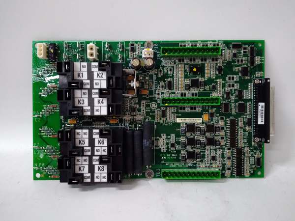
IS200AEADH4ADA
High-Frequency Troubleshooting FAQ
The board features standard status LEDs for power and I/O channel activity. A missing or blinking power LED usually points to a loss of the isolated 24VDC supply or a blown fuse on the backplane. If specific channel LEDs are erratic, check your shielded sensor cable grounding—poor shielding in an exciter cabinet will light up this board’s diagnostics instantly.
Generally, no. Because this board interfaces directly with high-energy excitation circuits, standard safety procedure dictates that you must de-energize the exciter system and verify zero energy state before pulling or inserting this module. Hot-swapping risks massive arcing and will likely destroy the new card and potentially the backplane.
Why am I getting noisy analog readings on my exciter voltage feedback?
First, check your physical grounding. The relies on excellent cabinet grounding. If the ground is solid, dive into your software configuration. Ensure the software filter cutoff frequency isn’t set too high (letting noise through) or too low (causing phase lag). Adjusting the cutoff between 3 Hz and 6 Hz is a common field fix for exciter noise issues.
Commercial Availability & Pricing
Please note: The listed price is not the actual final price. It is for reference only and is subject to appropriate negotiation based on current market conditions, quantity, and availability.