
Description
Hard-Numbers: Technical Specifications
- Redundancy Link: Fiber optic (HSSB) high-speed serial bus
- Switchover Time: <50 ms (automatic failover)
- Supported CPU Models: IC698PSA140 (Pentium III), IC698CPE040 (Pentium III)
- Throughput: Up to 10 Mbps on redundancy link
- Fiber Type: Multi-mode fiber (62.5/125μm or 50/125μm)
- Maximum Fiber Length: 2 km (6,561 feet) between redundant racks
- Operating Temperature: 0°C to 60°C (32°F to 140°F)
- Storage Temperature: -40°C to 85°C (-40°F to 185°F)
- Power Draw: 600mA @ 5VDC from backplane
- Backplane Current: 5V: 600mA max
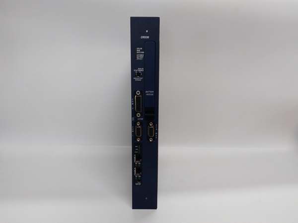
- LED Indicators: PWR, RUN, OK, FAULT, SYNC (link status), ACT (data active)
- Module Slot: Universal RX7i backplane slot (any position, typically adjacent to CPU)
- Isolation: 500V RMS between redundancy interface and backplane
- Data Synchronization: Full program, variables, I/O states, and diagnostics mirrored
- Firmware Version: Compatible with Proficy Machine Edition v6.0 and later

GE IC698CRE030
The Real-World Problem It Solves
In critical infrastructure, a CPU failure means a plant shutdown. The IC698CRE030 enables automatic redundancy—your backup CPU takes over within 50ms if the primary fails. Operators never notice, and your process keeps running while you service the failed unit.
Where you’ll typically find it:
- Power plant turbine control systems requiring bumpless transfer on CPU failure
- Water treatment SCADA systems where downtime affects service to millions
- Chemical process plants running critical reactions that cannot be interrupted
Bottom line: It buys you high availability with sub-50ms switchover that keeps your plant alive.
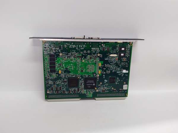
Hardware Architecture & Under-the-Hood Logic
The IC698CRE030 is the bridge between paired redundant CPUs in separate RX7i racks. Each CPU rack has its own CRE module, and the two CRE modules communicate via fiber optic HSSB (High-Speed Serial Bus) link. The active CPU executes control logic and drives the I/O backplane. The standby CPU shadows execution and continuously receives synchronized data from the active CPU via the CRE modules. Synchronization includes program memory, variable tables, I/O states, timer/counter values, and diagnostic information. The CRE module monitors health signals from both CPUs and controls switchover logic. If the active CPU fails (hardware fault, watchdog timeout, or manual switchover command), the CRE module triggers a handoff—the standby CPU assumes control of its local I/O backplane within 50ms. The fiber link provides galvanic isolation between racks, eliminating ground loops and electrical noise issues.
Internal signal flow:
- Both CPUs power up and initialize their respective CRE modules
- CRE modules exchange handshake via fiber HSSB link
- Primary CPU assumes active role; secondary enters standby monitoring mode
- Active CRE module transmits sync data to standby CRE (continuous mirroring)
- Synchronization includes: program memory, variables, I/O table, timers, counters
- Both CRE modules exchange heartbeat packets every 10ms
- Standby CRE receives sync data and updates standby CPU memory tables
- Standby CPU runs shadow logic but does not drive I/O outputs
- On primary CPU fault or manual switchover command, CRE modules execute handoff
- Standby CRE signals standby CPU to assume active mode
- Active CRE takes control of backplane I/O within 50ms; primary enters fault state
GE IC698CRE030
Field Service Pitfalls: What Rookies Get Wrong
Failing to match CPU firmware and CRE firmware versionsI’ve seen technicians replace a failed CPU with a spare running different firmware than the CRE module. The redundancy link never synchronizes, and switchover fails when needed. You end up with a backup that can’t take over.
- Field Rule: Both CPUs must run identical firmware versions, and both CRE modules must run identical firmware versions. The CPU firmware must be compatible with the CRE firmware. Check all firmware revisions in Machine Edition before installation. If mismatched, flash all components to matching versions before enabling redundancy.
Using copper instead of fiber causes ground loop failuresThe IC698CRE030 supports both copper and fiber HSSB links, but I’ve seen technicians use copper to save money. When racks are in different buildings or separated by significant distance, ground differentials between racks corrupt the link and cause synchronization loss.
- Field Rule: Always use multi-mode fiber for the HSSB link between racks. Fiber provides galvanic isolation and eliminates ground loops. Use fiber with proper LC or ST connectors as specified by the CRE module. Only use copper if racks are in the same cabinet and bonded to the same ground reference—and even then, fiber is preferred for reliability.
Incorrect module placement causes backplane conflictsThe IC698CRE030 must be installed in the correct backplane slot for proper communication with the CPU. I’ve seen technicians plug the CRE into slot 5 and wonder why it can’t talk to the CPU in slot 1.
- Field Rule: Install the CRE module immediately adjacent to the CPU module in the backplane. The CRE and CPU communicate via dedicated backplane connections that require specific slot positioning. Follow the RX7i hardware configuration guidelines—typically CPU in slot 0 or 1, CRE in the adjacent slot. Never install other modules between the CPU and CRE.
Forgetting to configure redundancy in softwareHardware alone won’t make it work. I’ve seen technicians wire everything correctly but leave the CPUs in standalone mode. When the primary fails, the backup sits idle and the plant goes down.
- Field Rule: Configure CPU redundancy in Proficy Machine Edition hardware configuration. Enable “Redundancy” on both CPUs and assign primary/standby roles. Configure the CRE modules as redundancy partners. Download configuration to both CPUs and verify synchronization status via the online diagnostics. Test switchover by pulling power from the primary CPU—watch the backup take control.
Ignoring fiber cable maintenance causes intermittent failuresI’ve seen plants run for years without touching the fiber HSSB cables. Dust, connector contamination, and cable damage cause intermittent link losses. The CRE modules show SYNC faults, and redundancy 终止s working.
- Field Rule: Inspect fiber cables quarterly. Clean LC/ST connectors with proper fiber cleaning kits. Replace damaged cables immediately. Document cable routes and avoid tight bends (<30mm radius). Use patch panels for easy cable replacement without disturbing the PLC rack. Test fiber attenuation with an optical power meter annually—should be under 3dB for 2km multi-mode fiber.
Neglecting switchover testing leads to surprisesRedundancy systems often sit untouched for years. When the primary CPU finally fails, switchover should work—but often doesn’t because the configuration was never tested or the firmware drifted over time.
- Field Rule: Test automatic switchover during commissioning and annually thereafter. Simulate a primary CPU failure by removing power or tripping its circuit breaker. Verify the standby CPU assumes control within 50ms. Document switchover time and verify I/O states transfer correctly. Don’t wait for a real failure to discover your redundancy isn’t working.
Commercial Availability & Pricing Note
Please note: The listed price is for reference only and is not binding. Final pricing and terms are subject to negotiation based on current market conditions and availability.


