

Description
Hard-Numbers: Technical Specifications
- Input Voltage Range: 85-264VAC, single-phase, 47-63Hz (auto-ranging)
- Input Current: 4A @ 120VAC, 2A @ 240VAC full load
- Output Voltage +5VDC: 5.1VDC nominal, regulated
- Output Current +5VDC: 15A continuous
- Output Voltage +12VDC: 12VDC nominal, regulated
- Output Current +12VDC: 0.5A continuous
- Total Power Output: 80W (75W +5V, 6W +12V)
- Efficiency: 75% typical at full load
- Hold-up Time: 20ms minimum at full load
- Operating Temperature: 0°C to 60°C (32°F to 140°F)
- Storage Temperature: -40°C to 85°C (-40°F to 185°F)
- Overcurrent Protection: Current limiting on both +5V and +12V outputs
- Overvoltage Protection: Crowbar at +5.8VDC, latch-off on +12V overvoltage
- LED Indicators: PWR (OK), FAULT, OVERTEMP
- Cooling: Passive convection (no fan required)
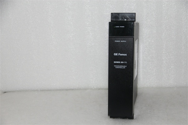
- Module Slot: Series 90-70 dedicated power supply slot (leftmost position)
- Isolation: 2500V RMS input-to-output isolation

GE IC697PWR711
The Real-World Problem It Solves
Not every plant has clean, stable AC power. The IC697PWR711 accepts a wide input voltage range—85VAC to 264VAC—so it works globally and tolerates brownouts without dropping your controller. It delivers reliable 5VDC logic power for your PLC rack and 12VDC for analog modules needing reference voltage.
Where you’ll typically find it:
- Legacy Series 90-70 PLC racks in water treatment control panels
- Paper mill drive systems where voltage sags occur during motor starts
- International installations where 240VAC is the standard plant voltage
Bottom line: It’s a workhorse supply that tolerates dirty AC power and keeps your rack running.
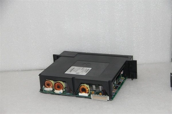
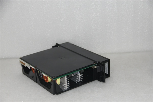
Hardware Architecture & Under-the-Hood Logic
This is a switch-mode power supply (SMPS) that converts AC line voltage into regulated +5VDC and +12VDC outputs. The input stage includes an EMI filter, bridge rectifier, and bulk capacitor bank to smooth the rectified DC. A PWM controller drives switching transistors at 20-40kHz, stepping down the voltage through a multi-winding ferrite core transformer. The +5VDC output is tightly regulated using feedback from the secondary side and provides the main power for the backplane and I/O modules. The +12VDC output is derived from a separate transformer winding and provides reference voltage for analog modules. Both outputs include overcurrent protection via current limiting and overvoltage protection via crowbar circuits. The FAULT LED triggers if either output exceeds safe thresholds.
Internal signal flow:
- AC input (85-264V) passes through EMI filter and line fuse
- Bridge rectifier converts to DC; bulk capacitors smooth ripple
- PWM controller senses input voltage and adjusts duty cycle for auto-ranging
- Switching transistors chop DC at high frequency into transformer primary
- Transformer steps down voltage via two secondary windings
- +5V winding feeds rectifier diodes and LC filter for regulated +5VDC output
- +12V winding feeds separate rectifier and filter for regulated +12VDC output
- Voltage feedback loops sample both outputs and adjust PWM to maintain regulation
- Current sense resistors monitor load; protection circuits trigger on fault
- Crowbar fires SCR if +5V exceeds 5.8V, protecting backplane
- LED indicators reflect health of each protection stage and output status
GE IC697PWR711
Field Service Pitfalls: What Rookies Get Wrong
Overloading the 5V rail causes random module faultsI’ve seen racks stuffed with high-density I/O modules that collectively draw more than 15A. Technicians keep adding cards without checking the power budget, and the supply hits current limit. The voltage sags, modules brown out, and you get random faults that look like hardware failures.
- Field Rule: Sum the 5V current requirements of all modules in the rack. The IC697PWR711 delivers 15A max at +5V. If your total exceeds 12A continuous, install a second power supply and use a power distribution module to split the load. Never operate at 100% capacity continuously—aim for 75% max loading for reliability.
Forgetting to use the power distribution module in multi-supply racksWhen you add a second IC697PWR711 to handle high-current racks, I’ve seen technicians plug both supplies directly into the backplane without isolating them. This creates a ground loop between the two supplies and can cause both to fault out.
- Field Rule: Always use the IC697PWR711 with the IC697PWR001 power distribution module when installing multiple supplies. The distribution module provides isolation and current balancing between supplies. Never wire two IC697PWR711s directly in parallel without the distribution module—you’ll cook one or both.
Ignoring the 12V output requirement causes analog driftAnalog modules like IC697ALG230 need the 12V reference for accurate conversions. I’ve seen technicians replace the IC697PWR711 with a 5V-only supply and wonder why their 4-20mA readings drift by 5%.
- Field Rule: If your rack contains any analog modules, you need the 12V output from the IC697PWR711. Check your analog module specs—most require +12V reference for analog-to-digital conversion. Never substitute with a 5V-only supply. Verify 12V output with a multimeter during commissioning—should be 11.4-12.6VDC at full load.
Wiring input power without surge protectionIndustrial AC lines are hostile environments. I’ve replaced countless IC697PWR711s after lightning strikes or nearby VFD switching caused massive voltage spikes. The input filter helps, but it’s not a surge protector.
- Field Rule: Install a MOV-based surge suppressor or TVSS (Transient Voltage Surge Suppressor) upstream of the PLC cabinet. For harsh environments, use a metal-clad AC (MC) cable for input wiring with proper grounding. Keep AC wiring separated from low-voltage DC wiring in the cabinet—run in separate conduit trays.
Missing the ground bond causes erratic behaviorThis supply requires a solid earth ground reference for proper operation and EMI suppression. I’ve seen technicians leave the ground floating, resulting in intermittent faults and erratic analog readings.
- Field Rule: Bond the module’s chassis ground terminal to a solid earth ground. Use a green ground conductor sized per NEC—typically #12 AWG or larger. Verify continuity to building steel with less than 5 ohms resistance. Never float the ground or rely on conduit alone for grounding.
Commercial Availability & Pricing Note
Please note: The listed price is for reference only and is not binding. Final pricing and terms are subject to negotiation based on current market conditions and availability.


