
Description
Hard-Numbers: Technical Specifications
- Input Voltage Range: 0-30VDC (nominal 24VDC)
- Input Current per Point: 7.5 mA typical at 24VDC
- ON Voltage Threshold: 15-30VDC
- OFF Voltage Threshold: 0-5VDC
- Input Impedance: 3.2 kΩ typical
- Response Time: 1-15 ms programmable (default 7 ms)
- Points per Module: 32 (isolated groups of 8)
- Module Power Draw: 250mA @ 5VDC from backplane
- Backplane Current: 5V: 250mA max
- Isolation: 1500V RMS between input groups and backplane, 250V RMS between groups
- LED Indicators: 32 individual point LEDs, module status LED
- Input Filter: Configurable 1ms, 3ms, 7ms, or 15ms
- Operating Temperature: 0°C to 60°C (32°F to 140°F)
- Storage Temperature: -40°C to 85°C (-40°F to 185°F)
- Connector Type: 40-pin terminal block (IC697TBB132)
- Wire Size: 16-28 AWG solid or stranded
- Inrush Current: None (current-limited inputs)

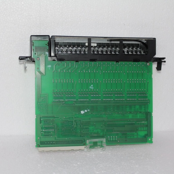
GE IC697MDL654
The Real-World Problem It Solves
High-density input requirements are common in panel builds with limited cabinet space. The IC697MDL654 packs 32 inputs into a single module, reducing rack space and wiring complexity. Its configurable filter settings adapt to different sensor types, eliminating false triggers from electrical noise.
Where you’ll typically find it:
- Assembly machine control panels with dozens of proximity sensors and limit switches
- Material handling systems monitoring photoeyes and position sensors
- Packaging lines tracking multiple safety interlocks and status inputs
Bottom line: It gives you maximum point density in minimal space, with filtering flexibility for noisy environments.
Hardware Architecture & Under-the-Hood Logic
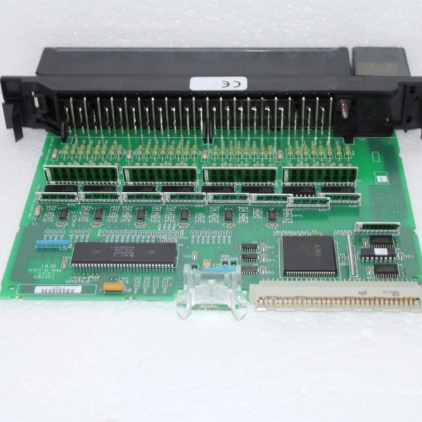
The IC697MDL654 uses optoisolators for each input point to protect the PLC backplane from external voltage transients. Each group of 8 inputs shares a common return reference, providing isolation between groups. The module includes digital filtering circuitry configurable via CPU software to debounce input signals. Input status is stored in an internal register and transmitted to the CPU via the backplane during each scan cycle. The LED indicators are driven directly from the optoisolator outputs, giving real-time visual feedback independent of CPU communication. The module supports programmable input response times to match sensor characteristics—fast response for counters, slower response for noisy contacts.
Internal signal flow:
- External 24VDC signal from field device arrives at terminal block
- Signal passes through input filter (configurable RC network)
- Current-limited signal drives optoisolator LED
- Optoisolator phototransistor switches, creating isolated logic signal
- Logic signal is latched into input register
- Input status is buffered for backplane transmission
- Module exchanges input data with CPU via backplane memory window
- CPU reads input states during I/O scan and updates program logic
- Point LEDs are driven by optoisolator outputs for local indication
- Module continuously monitors input voltage and reports faults if out-of-range
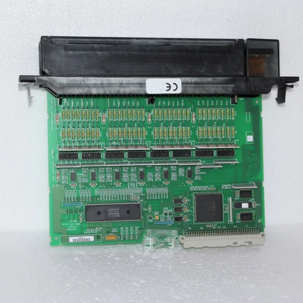
GE IC697MDL654
Field Service Pitfalls: What Rookies Get Wrong
Mixing different sensor types on the same module causes inconsistent behaviorI’ve seen technicians wire PNP sensors on group 1 and NPN sensors on group 2, then wonder why half the inputs read incorrectly. The IC697MDL654 expects sinking inputs to a common return—mixing sourcing and sinking devices creates ground reference conflicts.
- Field Rule: Use only sinking (NPN) sensors on the same module. Ensure all field devices share the same common return reference. If you must use PNP sourcing sensors, use an interposing relay or select a sourcing input module like IC697MDL750. Don’t mix sensor types on the same module without external conversion.
Improper grounding creates phantom inputsWhen the common return for an input group is floating or tied to a different ground reference than the PLC, I’ve seen random inputs turn on when they shouldn’t. Ground differentials cause the optoisolators to conduct, creating false signals that drive maintenance teams crazy.
- Field Rule: Connect all input commons to the same PLC cabinet ground reference. Use a single-point ground scheme for the entire PLC rack. If sensors are located remotely, run a dedicated common conductor back to the PLC—never rely on conduit or machine frame as your return path. Measure ground potential between sensor commons and PLC ground—should be less than 0.5VAC.
Wrong filter setting creates missed counts or false triggersThe input filter is adjustable for a reason. I’ve seen technicians leave the default 7ms filter on high-speed counter inputs, causing missed counts from fast photoeyes. Conversely, setting 1ms filtering on limit switch inputs creates false triggers from contact bounce.
- Field Rule: Match filter setting to your application. High-speed counters and encoders: 1-3ms. General-purpose limit switches and proximity sensors: 7ms default. Noisy electromechanical switches in VFD-rich environments: 15ms. Configure filters in Machine Edition hardware setup and test with your actual field devices before going live.
Overvoltage destroys optoisolatorsThe IC697MDL654 is rated for 30VDC maximum. I’ve seen modules fail after someone wired 120VAC into an input terminal or connected a 48VDC sensor. The optoisolators fry instantly, sometimes taking the backplane with them.
- Field Rule: Verify field device voltage before wiring. Use 24VDC-rated sensors only. If you have 120VAC inputs, use an interposing relay or a dedicated AC input module like IC697MDL240. Install a fuse or PTC in the common return if voltage transients are possible in your application.
Forgetting to enable the module in configurationNew technicians often install the module and wire it correctly, then wonder why the CPU shows all inputs at zero. The IC697MDL654 must be enabled in the hardware configuration and assigned input references (%I) for the CPU to read it.
- Field Rule: Add the module to your hardware configuration in Machine Edition. Enable the module and assign %I addresses to all 32 points. Download configuration to CPU and verify input responses using the online monitoring tools. Document the assigned %I addresses in your PLC tag list for troubleshooting.
Wiring too small gauge causes voltage dropsI’ve seen inputs fail to turn on reliably because technicians used 24AWG wire for long sensor runs. The resistance causes voltage drop across the wire, leaving the input with less than the 15V needed for ON state.
- Field Rule: Size wire for voltage drop over distance. For runs under 100 feet, 22-24 AWG is fine. For runs 100-300 feet, use 18-20 AWG. For runs over 300 feet, consider remote I/O or use 24VDC power at the sensor location and return dry contacts to the PLC. Measure voltage at the input terminal during ON state—should be 15-30VDC.
Commercial Availability & Pricing Note
Please note: The listed price is for reference only and is not binding. Final pricing and terms are subject to negotiation based on current market conditions and availability.


