
Description
Hard-Numbers: Technical Specifications
- Input Channels: 16 differential analog inputs
- Voltage Input Range: -10 to +10V DC
- Input Impedance: >10 MΩ per channel
- Accuracy: ±0.03% of full scale ±0.02% of reading
- Conversion Rate: 2 ms per channel
- Calibration: Factory set at 10V ±2mV
- Power Requirement: 0.4 Amps (2 watts) at +5V DC
- Backplane Isolation: All inputs isolated from module backplane
- Field Power: No external power required for field side
- Maximum Input Configurations: 120 inputs (via daisy-chain of 7 modules)
- Wiring Compatibility: AWG 22 to 14 wire sizes on removable terminal board
- Mounting: Series 90-70 standard rack module form factor
- Error Rate: ±0.03% of full value ±0.02% of reading
- Conversion Resolution: 14-bit A/D with oversampling averaging

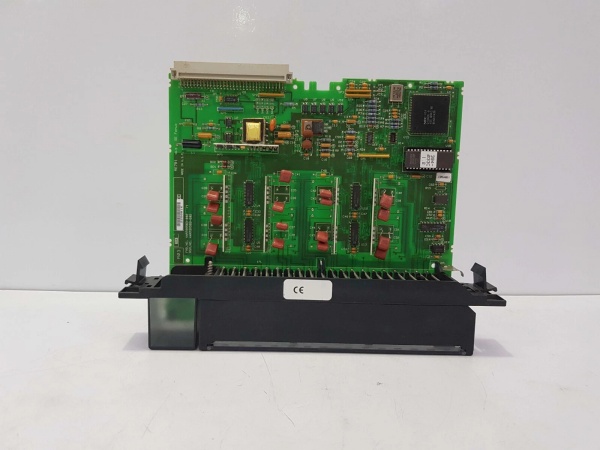
GE IC697ALG441
The Real-World Problem It Solves
The IC697ALG441 solves the challenge of expanding analog input capacity in Series 90-70 PLC systems cost-effectively. Traditional expansion methods required replacing primary controller modules or adding expensive additional racks, but this module enables incremental analog channel expansion with per-point costs as low as 1/3 of primary rack configurations. It also eliminates the need for jumpers or DIP switches, reducing configuration time and human error by over 90% compared to competing analog expansion solutions. Without this module, users would face costly system reconfigurations or be forced to limit analog measurement points, reducing process visibility and control precision.
Where you’ll typically find it:
- Process Manufacturing Plants: Expanding temperature, pressure, and level measurement inputs in chemical, pharmaceutical, or food and beverage production lines.
- Power Generation Facilities: Monitoring turbine exhaust temperatures, steam pressures, and vibration levels in gas turbine power plants using Series 90-70 control systems.
- Water/Wastewater Treatment: Adding flow rate and pH measurement channels to existing control systems without needing rack upgrades.
- Oil and Gas Production: Monitoring pipeline pressures, tank levels, and process temperatures in upstream and midstream oil and gas operations.
Bottom-line value: Provides flexible, cost-effective analog input expansion, allowing users to scale process measurement capabilities incrementally without major controller upgrades—critical for maintaining control system relevance as plant processes expand and evolve over time.
Hardware Architecture & Under-the-Hood Logic
The IC697ALG441 is an analog input expansion module designed to pair with the Series 90-70 base converter module (IC697ALG230). It contains 16 high-impedance differential analog input channels, each with dedicated signal conditioning circuitry and overvoltage protection. The module performs analog-to-digital conversion using a 14-bit ADC with 2ms per-channel throughput. The differential input design provides excellent noise rejection from common-mode interference sources such as long cable runs and electrical motors. Data is presented as 2’s complement format (sign + 15 bits) to the PLC CPU. The module can be daisy-chained with up to six other expander modules to support up to 120 total analog inputs. All calibration is factory-set with ±2mV accuracy, eliminating the need for field calibration. Configuration is done via Windows programming software without requiring DIP switches or jumper settings.
Internal Signal Flow:
- Input Signal Reception: ±10V analog signals arrive via removable terminal board with AWG 22-14 wire compatibility.
- Overvoltage Protection: Each input channel includes transient voltage suppression to protect the module from high-energy spikes up to ±100V.
- Signal Conditioning: Low-pass filtering and amplification stages condition the input signal to optimize ADC performance and reject high-frequency noise.
- Differential-to-Single-Ended Conversion: Differential inputs are converted to single-ended signals for ADC processing, providing >60dB common-mode noise rejection.
- 14-Bit ADC Conversion: A high-speed ADC performs analog-to-digital conversion at 2ms per channel, with oversampling averaging enhancing resolution beyond 14 bits.
- Data Formatting: Converted values are formatted as 2’s complement (16-bit word) for transmission to the base converter module and PLC CPU.
- Backplane Communication: Processed data is transferred via the backplane communication bus to the base converter, which handles overall subsystem management and scaling factor application.
GE IC697ALG441
Field Service Pitfalls: What Rookies Get Wrong
Attempting to Use IC697ALG441 as a Standalone Module
The IC697ALG441 is an expander module that requires pairing with a base converter module (IC697ALG230) to function properly. Technicians frequently try to install the module directly into a rack slot and expect it to work without the necessary base converter. This results in no communication with the PLC CPU and no analog data being processed. The expander module relies on the base converter for power distribution, signal routing, and scaling factor management.
- Field Rule: Always install IC697ALG441 expander modules with a matching IC697ALG230 base converter module. Never install an expander module in a rack slot without a properly configured base converter. Verify the base converter’s firmware is compatible with the expander module revision before commissioning.
Mismatched Scaling Factors Across Expander Modules
A common mistake is configuring different scaling factors across multiple daisy-chained expander modules when they should be reading from the same type of sensor input. This causes inconsistent data interpretation by the PLC, with signals from different racks reading differently despite identical physical values. I’ve seen systems reject batch processing because temperature readings from two expander modules were scaled differently, making the process appear out of spec when it wasn’t.
- Quick Fix: Apply a consistent scaling factor across all expander modules that read the same type of sensor data (e.g., all temperature inputs use 0-100°C scaling). Configure scaling via the Series 90-70 programming software rather than attempting to adjust via jumpers or DIP switches (which don’t exist on this module). Verify scaling consistency by injecting a known reference signal into each module and confirming similar output values.
Ignoring Cable Length and Noise Limits
While the IC697ALG441 features excellent noise rejection, novice technicians often run sensor cables hundreds of feet beyond recommended limits without proper cable selection. The differential inputs can tolerate some noise, but cables longer than 100 meters running in parallel with power lines or VFD cables will inject common-mode noise that the module can’t fully reject, leading to noisy and unstable readings. I’ve seen units fluctuate by ±5% of full scale due to unshielded cables run near 480V motor leads.
- Field Rule: Use shielded twisted-pair cable rated for industrial environments with cable lengths kept <100 meters for voltage inputs (less for 4-20mA current signals). Ground cable shields at one end only, typically at the module terminal board, not at both ends or at sensor locations. Run analog signal cables in separate conduit or trunking from power cables and high-frequency switching equipment.
Mixing Input Types Within an Expander Module
The IC697ALG441 is a voltage-specific expander module, but technicians sometimes connect 4-20mA current inputs to it by configuring resistor networks. While technically possible, this practice compromises accuracy and introduces drift from resistor temperature coefficient changes. Mixing voltage and converted current inputs on the same module also makes troubleshooting difficult, as voltage readings appear at different scales than converted current readings despite being processed by the same scaling factor.
- Field Rule: Use dedicated voltage expander modules for voltage inputs and dedicated current expander modules (IC697ALG330 series) for current inputs. If mixing is unavoidable, use external current-to-voltage converters with high-stability resistors (±0.1% accuracy) and create separate scaling factors for converted current channels. Label converted current channels clearly in the PLC tag database to avoid confusion with native voltage inputs.
Commercial Availability & Pricing Note
Please note: The listed price is for reference only and is not binding. Final pricing and terms are subject to negotiation based on current market conditions and availability.


