
Description
Hard-Numbers: Technical Specifications
- Input Voltage Range: 18 to 30 VDC (nominal 24 VDC)
- Input Power: 60 Watts maximum at full load
- Output Power: 40 Watts maximum total (5.1VDC = 30W max, 3.3VDC = 30W max, combined total ≤40W)
- Output Voltage: 5.1 VDC (5.0-5.25 VDC), 3.3 VDC (3.2-3.465 VDC)
- Output Current: 5.1VDC = 0-6 Amps, 3.3VDC = 0-9 Amps
- Overcurrent Protection: 5.1VDC limited to 7A, 3.3VDC limited to 10A
- Inrush Current: 4 Amps peak, 100 milliseconds maximum
- Ride-Through Time: 10 milliseconds minimum
- Ripple/Noise: 50mV maximum (all outputs)
- Isolation: None (input to backplane not isolated)
- Wiring Terminals: Accepts 14-22 AWG copper conductors (75°C minimum rating)
- Terminal Current Rating: 6 Amps per terminal
- Operating Temperature: 0°C to 60°C (derating required above 32°C)
- Number of Units per Backplane: Up to 4 PSD140 supplies
- Daisy-Chain Capability: Up to 4 supplies
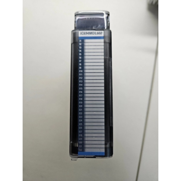
GE IC694MDL660
The Real-World Problem It Solves
24VDC-only industrial facilities—offshore platforms, remote pump stations, solar-powered sites—can’t use the standard 120/240VAC RX3i power supplies (IC695PSA140/PSA040). The IC695PSD140 bridges that gap, taking readily available 24VDC plant power and converting it to the 5.1VDC and 3.3VDC needed by the backplane logic.
Where you’ll typically find it:
- Offshore oil & gas platforms with 24VDC battery-backed distribution systems
- Remote wellhead controllers powered by solar arrays with 24VDC battery banks
- Retrofit jobs where facility power is 24VDC-only and pulling new AC circuits isn’t feasible
Bottom line: It’s the only path to deploy RX3i hardware in pure-DC facilities without adding a separate inverter stage.
Hardware Architecture & Under-the-Hood Logic
The IC695PSD140 is a non-isolated DC-DC converter. Unlike the PSA140 (which has transformer isolation from AC input to backplane), the PSD140 shares a common DC ground reference between input and output—no galvanic separation. This matters in floating or positive-grounded systems (see Field Pitfalls).
Internal signal flow:
- Input Stage: 18-30VDC feeds a surge limiter and EMI filter. The module has an internal fusable link as backup protection—primary overcurrent is electronic shutdown, not a field-replaceable fuse.
- DC-DC Conversion: Dual buck converters generate 5.1VDC and 3.3VDC rails. Both outputs share the 40W total budget; loading one rail heavily reduces available power on the other.
- Backplane Distribution: Outputs connect directly to the RX3i Universal Backplane power bus. No isolation barrier—input and output share ground reference.
- Monitoring & Protection: Internal sensors monitor output voltage, current, and temperature. Fault conditions (overvoltage, overcurrent, overtemperature) trigger shutdown and report to the CPU Fault Table.
- LED Indication: Four front-panel LEDs provide status: POWER (green/amber), P/S FAULT (red), OVERTEMP (amber), OVERLOAD (amber). Amber POWER LED = supply has input power but switch is OFF.
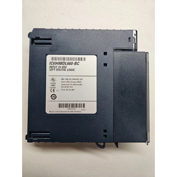
GE IC694MDL660
Field Service Pitfalls: What Rookies Get Wrong
No Input-to-Backplane Isolation—Ground Reference Critical
This module has zero galvanic isolation between the 24VDC input and the 5.1V/3.3V backplane outputs. In floating or positive-grounded DC systems (common in offshore and telecom), you can create ground loops or reverse-polarity faults that take down the entire backplane.
Field Rule: Verify the facility DC distribution grounding scheme before landing wires. If the 24VDC supply is floating or positive-grounded, install an external DC-DC isolator upstream, or switch to an isolated AC-powered supply with an inverter if isolation is required.
Thermal Derating Above 32°C—40W Rating Drops Fast
At 32°C ambient, you get the full 40W output. Above that, the derating curve kicks in hard. By 50°C, you’re looking at roughly 25W available. rookies see “40W” on the datasheet, load it to 38W in a 45°C MCC cabinet, and wonder why the OVERTEMP LED is glowing amber within an hour.
Field Rule: Calculate actual backplane power draw (sum all module 5V and 3.3V current specs), then check derating curve against worst-case cabinet temperature. If you’re within 10% of derated capacity, add ventilation or derate further.
Fault Latch Requires Power Cycle—No Auto-Restart in Redundancy Mode
This module is designed for redundant applications. When an overload or fault occurs, it latches OFF and will not attempt to auto-restart. You have to cycle input power to clear the fault. Rookies assume it’s “dead” and swap the module, when all it needed was a power cycle.
Quick Fix: If the P/S FAULT LED is red, cycle the external 24VDC source. If the fault clears, the module is fine—investigate the root cause (shorted I/O module, backplane bus fault, overload condition). If fault persists after power cycle, then suspect the supply.
Non-Redundancy Auto-Restart Option: There’s an internal shunt jumper location on the back of the module that enables auto-restart mode for non-redundant applications. Requires Radio Shack #276-1512 or Digi-Key #59000-ND shunt. Module must be removed from backplane to install—plan accordingly.
Cannot Mix with IC695PSD040 or IC695PSA040 in Redundancy/Capacity Mode
The PSD140 supports load sharing and redundancy, but ONLY with other PSD140 units. You cannot combine it with IC695PSD040 or IC695PSA040 supplies in a shared-backplane configuration—doing so will damage equipment.
Field Rule: If upgrading from a single PSD040 to redundant supplies, you must replace the PSD040 entirely with PSD140 units. Do not mix catalog numbers in the same backplane.
Overvoltage Protection Jumper Must Be Removed for Hi-Pot Testing
The bottom terminal has a jumper that connects internal MOV overvoltage protection devices to frame ground. For Hi-Pot testing, this jumper must be removed to avoid false failures. After testing, reinstall it—without it, the module has no input overvoltage protection.
Field Rule: Before Hi-Pot test, remove the frame ground jumper. Document this in the test procedure. Reinstall immediately after test. If the jumper is missing on a used module, replace it or add external MOV protection upstream.
Commercial Availability & Pricing Note
Please note: The listed price is for reference only and is not binding. Final pricing and terms are subject to negotiation based on current market conditions and availability.


