


Description
Hard-Numbers: Technical Specifications
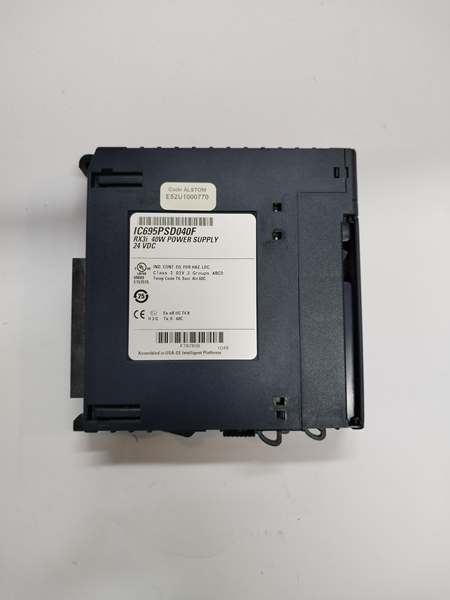
- Series: PACSystems RX3i
- Manufacturer: GE Fanuc / Emerson Automation (post-2019 acquisition)
- Module Type: Universal Base Power Supply
- Nominal Input Voltage: 24 VDC
- Input Voltage Range:
- Start Mode: 18 to 30 VDC
- Run Mode: 12 to 30 VDC
- Input Power (Maximum): 60 Watts at full load
- Output Power: 40 Watts maximum total
- 5.1 VDC output: up to 30 Watts maximum
- 3.3 VDC output: up to 30 Watts maximum
- Output Voltage Range:
- 5.1 VDC: 5.0 to 5.25 VDC (5.1 VDC nominal)
- 3.3 VDC: 3.2 to 3.465 VDC (3.3 VDC nominal)
- Output Current:
- 5.1 VDC: 0 to 6 Amps
- 3.3 VDC: 0 to 9 Amps
- Additional Output: 24 VDC for relay output modules (user-accessible)
- Ripple and Noise (All Outputs): 50 mV maximum
- Inrush Current: 4 Amps, 100 milliseconds maximum
- Ride-Through Time: 10 ms (maintains valid outputs during power interruption)
- Isolation: None (non-isolated)
- Wiring Terminals: Each terminal accepts one 14 AWG to 22 AWG wire
- Terminal Current Rating: 6 Amps
- LED Indicators: Power (Green/Amber), P/S Fault (Red), Over Temperature (Amber), Overload (Amber)
- On/Off Switch: Yes (located behind protective door on front panel)
- Slot Assignment: Slot 0 of RX3i universal backplane
- Daisy-Chaining: Supports up to two IC695PSD040 supplies connected (does NOT increase total output capacity)
- Installation Environment: Pollution Degree 2 only
- Operating Ambient Temperature: Derating applies; full 40W available up to at least 32°C (89.6°F). Consult thermal derating curve for higher temperatures
- Power Supply Redundancy: Not supported
- Increased Capacity Mode: Not supported
- Weight: Approximately 0.34 kg (0.75 lbs)
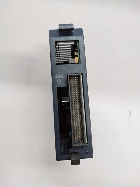
- Protective Casing: Blue streamlined housing
IC695PSD040
The Real-World Problem It Solves
Industrial PLC systems require stable, low-noise DC power to ensure reliable operation of controllers, I/O modules, and communication interfaces. Power fluctuations, voltage sags, and insufficient current capacity can cause unexpected system shutdowns, data corruption, or module failures. The IC695PSD040 provides regulated 5.1 VDC and 3.3 VDC outputs specifically designed for RX3i modules, with built-in ride-through capability to bridge brief input power interruptions. Diagnostic LEDs provide immediate status indication for power, faults, overtemperature, and overload conditions, enabling quick troubleshooting.
Where you’ll typically find it:
- Manufacturing assembly lines using RX3i PLCs
- Process control systems with 24 VDC distribution infrastructure
- Packaging machinery and material handling equipment
- Water/wastewater treatment plants with DC bus power
- Automotive manufacturing cells requiring stable logic-level power
Bottom line: It delivers clean, regulated DC power for RX3i modules with comprehensive diagnostics and protection features, ensuring system reliability in industrial environments.
Hardware Architecture & Under-the-Hood Logic
The IC695PSD040 converts 24 VDC input into regulated 5.1 VDC and 3.3 VDC outputs required by RX3i modules and backplane logic.
- Input Stage: Accepts 24 VDC nominal input (18-30 VDC start range; 12-30 VDC run range). An internal inrush current limiter restricts startup current to 4 A max for 100 ms to protect upstream DC supply.
- Power Conversion: Switching power supply topology efficiently converts input DC to isolated intermediate voltage, then regulates to 5.1 VDC and 3.3 VDC outputs via DC-DC converters. Total output power limited to 40 W; individual outputs capped at 30 W each.
- Output Regulation: Both 5.1 VDC (0-6 A) and 3.3 VDC (0-9 A) outputs are tightly regulated to maintain specified voltage ranges under varying loads. Ripple and noise limited to 50 mV to ensure clean power for sensitive logic circuits.
- 24 VDC Relay Output: An additional 24 VDC output is provided to energize circuits on relay output modules. This output is derived from the input and is available for user applications.
- Protection Circuits:
- Overcurrent Protection: 5.1 VDC electronically limited to 7 A; 3.3 VDC limited to 10 A. The supply shuts down on overload/short circuit and attempts auto-restart when fault is cleared.
- Overvoltage Protection: Internal circuitry clamps output voltage if regulation is lost.
- Thermal Protection: Internal temperature monitoring shuts down the supply if maximum operating temperature is exceeded.
- Internal Fuse: Non-repairable fusible link in the input line provides backup protection against catastrophic faults.
- Diagnostics:
- Power LED: Green = normal operation; Amber = input power applied but output switch off.
- P/S Fault (Red): Power supply failure detected (insufficient output voltage).
- Over Temperature (Amber): Near or exceeding maximum temperature.
- Overload (Amber): Output current near or exceeding maximum on at least one output.
- Ride-Through: Internal capacitance provides 10 ms of hold-up time to maintain outputs during brief input power interruptions. Note: When used with IC694/IC693 relay output modules, input voltage sags may cause relay dropout; take precautions if ride-through time is insufficient.
- Daisy-Chaining: Up to two IC695PSD040 supplies can be connected in parallel to share input power wiring; this does NOT increase total output capacity (each supply operates independently).
- Installation: The module occupies Slot 0 of the RX3i universal backplane. Only one IC695PSD040 may be installed per backplane; redundancy and increased capacity modes are not supported. If load exceeds 40 W, additional modules must be installed in expansion/remote backplanes.

IC695PSD040
Field Service Pitfalls: What Rookies Get Wrong
Exceeding Total Output PowerRookies calculate current per output independently and load both 5.1 VDC and 3.3 VDC outputs to their maximum (6 A and 9 A), ignoring the 40 W total limit. This overloads the supply and causes frequent shutdowns or reduced reliability.
- Field Rule: Never exceed 40 W total output power. If 5.1 VDC is at 30 W (5.9 A), the 3.3 VDC output can only supply 10 W (3 A). Check both current and power limits during system design.
Operating Below Minimum Start VoltageInstallers use a 24 VDC supply that sags below 18 VDC during startup due to high inrush currents from other equipment. The IC695PSD040 fails to start or repeatedly cycles.
- Quick Fix: Ensure the upstream 24 VDC source can maintain at least 18 VDC during startup under worst-case load. If voltage sag is unavoidable, consider a separate input source for the PLC power supply or use a DC UPS to buffer voltage.
Ignoring Temperature DeratingTechnicians install the IC695PSD040 in hot enclosures (above 40°C) without accounting for thermal derating. The supply overheats, triggers Over Temperature LED, and shuts down unexpectedly.
- Field Rule: Refer to the thermal derating curve in the manual. Above 32°C (89.6°F), output power must be reduced. Provide adequate ventilation or use a higher-wattage power supply (e.g., IC695PSD180) for high-ambient applications.
Over-Tightening Wiring TerminalsRookies apply excessive torque to terminal screws, damaging the internal clamps or breaking the wire strands. This creates high-resistance connections, leading to voltage drops and overheating.
- Quick Fix: Use a torque screwdriver set to 4.4 in-lb (0.5 N-m) for terminal connections. Ensure proper wire stripping length (typically 6-8 mm) and use only copper conductors (14-22 AWG). Avoid aluminum wires.
Misunderstanding Daisy-Chaining BenefitsInstallers assume daisy-chaining two IC695PSD040 supplies doubles the available output power. They load both supplies to 40 W each and expect 80 W total, leading to overloading and shutdowns.
- Field Rule: Daisy-chaining only shares the input power source; it does NOT increase output capacity. Each supply operates independently and is limited to 40 W. For higher power requirements, use a higher-wattage supply or distribute modules across multiple backplanes with individual power supplies.
Improper Grounding in Non-Isolated SystemsTechnicians treat the IC695PSD040 as an isolated supply and create multiple ground references. Since this module is non-isolated, improper grounding causes ground loops, noise, or unexpected equipment behavior.
- Field Rule: Connect the power supply input ground terminal to the common system ground as specified. Do not create separate ground references on the output side. Ensure all RX3i backplanes in the system share a common ground.
Sources:
- Emerson Automation – PACSystems RX3i Power Supply Product Page
- GE Fanuc RX3i System Manual (GFK-2314)
- IC695PSD040 Datasheet and Technical Specifications
Please note: The listed price is for reference only and is not binding. Final pricing and terms are subject to negotiation based on current market conditions and availability.


