
Description
Hard-Numbers: Technical Specifications
| Parameter | Specification |
|---|---|
| Number of Channels | 16 single-ended or 8 differential inputs |
| Input Ranges – Current | 0 to 20mA, 4 to 20mA, ±20mA |
| Input Ranges – Voltage | ±10V, 0 to 10V, ±5V, 0 to 5V, 1 to 5V |
| HART Protocol | Version 5.0 supported on each channel |
| HART Modems | 4 internal modems (ALG628 has 2 modems) |
| HART Multiplexing | Single-ended: 4 channels per modem; Differential: 2 channels per modem |
| ADC Resolution | 24-bit converted to Floating Point or Integer |
| Data Format | IEEE 32-bit floating point or 16-bit integer (in 32-bit field) |
| Filter Options | 8Hz, 12Hz, 16Hz, 40Hz, 200Hz, 500Hz |
| Input Impedance (Voltage) | >100 kΩ |
| Current Input Resistance | 249Ω ±1% |
| Open Circuit Detection | 1 second maximum (voltage and 4-20mA inputs) |
| Overvoltage Protection | ±60 VDC continuous maximum |
| Overcurrent Protection | ±28mA continuous maximum |
| Normal Mode Noise Rejection | 8Hz: 103dB @ 50Hz, 97dB @ 60Hz; 12Hz: 94dB @ 50Hz, 89dB @ 60Hz |
| Common Mode Noise Rejection | 120dB min @ 50/60Hz with 8Hz filter; 110dB min @ 50/60Hz with 12Hz filter |
| Channel-to-Channel Crosstalk | -80dB min (single-ended; differential grounded common); -60dB min (differential floating common) |
| Calibrated Accuracy @ 13-33°C | ±5V, ±10V, ±20mA: 0.05%; 0-10V, 0-5V, 1-5V, 0-20mA: 0.1%; 4-20mA: 0.125% |
| Calibrated Accuracy @ 0-60°C | 0-10V, 0-5V, 1-5V: 0.2%; 0-20mA: 0.25%; ±5V, ±10V: 0.1%; ±20mA: 0.125%; 4-20mA: 0.3125% |
| Calibration Interval | 12 months typical |
| Analog Module Scan Time | 3-482ms (depends on filter and acquisition cycles) |
| HART Data Update Time | 0.7-4.0 seconds typical (depends on devices per group) |
| Backplane Power Requirements | 5.0V: 600mA max; 3.3V: 625mA max |
| Power Dissipation | 7.35W maximum |
| Thermal Derating (Voltage Mode) | None |
| Thermal Derating (Current Mode) | See derating table (4-16 channels @ 50-60°C) |
| Terminal Block to Backplane Isolation | 250VAC continuous; 1500VAC for 1 minute |
| Terminal Blocks | IC694TBB032 (Box), IC694TBB132 (Extended Box), IC694TBS032 (Spring), IC694TBS132 (Extended Spring) |
| CPU Compatibility | RX3i CPU firmware version 3.5 or later |
| Programming Software | Proficy Machine Edition version 5.5 or later |
| Operating Temperature | 0°C to 60°C |
| Storage Temperature | -40°C to 85°C |
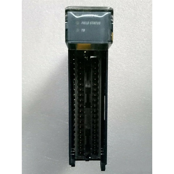
| LEDs | Module OK, Field Status, TB (Terminal Block) |
| Approvals | UL, UL HAZLOC, CE, ATEX C1D2, ABS, BV, DNV, GL, KRS, LR |
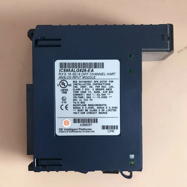
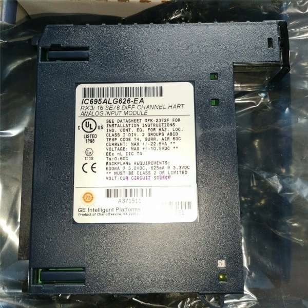
GE IC695ALG626
The Real-World Problem It Solves
This module eliminates the need for external HART multiplexers by integrating HART version 5.0 communication directly into each analog input channel, enabling simultaneous acquisition of process variables and digital diagnostics from smart instruments. Its four internal HART modems support up to 16 HART-enabled devices with intelligent multiplexing, reducing wiring complexity and installation cost while providing remote configuration and diagnostic capabilities.
Where you’ll typically find it:
- Chemical processing plants with HART-enabled pressure/temperature transmitters requiring remote calibration
- Oil & gas facilities using smart flow meters with HART diagnostics
- Pharmaceutical manufacturing with HART-enabled process analyzers
- Water treatment facilities with smart level transmitters requiring remote parameter access
Bottom line: It’s your integrated HART solution for high-density analog input applications requiring smart instrument communication without external HART interface hardware.
Hardware Architecture & Under-the-Hood Logic
The IC695ALG626 incorporates four internal HART modems with intelligent channel multiplexing. Each modem serves a group of four single-ended or two differential channels, enabling simultaneous analog measurement and HART communication. The module uses 24-bit sigma-delta ADCs with programmable hardware filtering and software-configurable scaling per channel.
Signal flow breakdown:
- HART-enabled field device (4-20mA transmitter) connects to terminal block
- Analog current signal (4-20mA with HART FSK modulation) enters module
- HART modem (one of four) extracts digital HART communication via Bell 202 modem
- A/D converter digitizes analog current signal (filtered per channel)
- Hardware filter (8-500Hz) removes electrical noise from analog path
- Digital value scaled per channel configuration (offset, engineering units)
- HART data processed separately: Command #33 reads slot variables, pass-thru commands available
- Combined analog and HART data stored in dual-port memory
- CPU reads analog values via %AI addresses during input scan
- HART data available via separate HART Reference addresses (%I/%Q/%AI/%AQ/%R/%W/%G/%M/%T)
- Diagnostics circuitry monitors for open wire, over/under range, rate-of-change
- Alarm/status bits updated in diagnostic reference memory
- Module status (OK LED, Field Status LED, TB LED) reflects health
- Hot-swap detection monitors terminal block presence/absence
HART modem architecture:
- 4 internal modems supporting HART version 5.0 protocol
- Single-ended mode: 4 channels multiplexed per modem (groups: 1-4, 5-8, 9-12, 13-16)
- Differential mode: 2 channels multiplexed per modem (groups: 1-2, 3-4, 5-6, 7-8)
- HART scan time: 0.7s (1 device/group) to 4.0s (4 devices/group)
- HART data modes: No data, Dynamic data only (18 words/288 bits), All data (88 words/1408 bits)
Acquisition cycle mapping (for fastest performance):
- Cycle 1: Channels 1, 5, 9, 13
- Cycle 2: Channels 2, 6, 10, 14
- Cycle 3: Channels 3, 7, 11, 15
- Cycle 4: Channels 4, 8, 12, 16

GE IC695ALG626
Field Service Pitfalls: What Rookies Get Wrong
HART Channel Selection MisunderstandingTechnicians enable HART on channels 1, 2, 3, 4, forcing all four devices into one modem group, causing slow HART update times (4.0 seconds).
- Field Rule: Distribute HART devices across modem groups for optimal performance. For 4 HART devices on ALG626, connect to channels 1, 5, 9, 13 (one device per group, 0.7s update). For 8 devices, use channels 1, 2, 5, 6, 9, 10, 13, 14.
Ignoring 4-20mA Requirement for HARTProgrammers configure channels for 0-20mA or voltage ranges expecting HART communication, which fails because HART requires 4-20mA mode.
- Field Rule: HART communications can only be enabled on channels configured for 4-20mA current range. Enabling HART forces the channel into 4-20mA operation. Voltage inputs (±10V, 0-10V, etc.) cannot support HART FSK modulation.
Slot Variables Enabling Without NeedDevelopers enable HART Slot Variables globally, doubling HART scan times (up to 8.0 seconds per group) when not needed.
- Field Rule: Enable Slot Variables only when requiring periodic automatic reading of transmitter variables via command #33. Use Pass-Thru Only mode for on-demand HART communication, reducing scan overhead. Slot variables disabled = normal HART scan; enabled = double time.
Thermal Derating Overlook in Current ModeInstallers run all 16 current inputs at 60°C ambient temperature, exceeding module’s thermal derating limits.
- Field Rule: Observe thermal derating table for current mode: 4 channels @ 60°C, 6 channels @ 58°C, 8 channels @ 57°C, 10 channels @ 55°C, 12 channels @ 54°C, 14 channels @ 52°C, 16 channels @ 50°C. No derating required for voltage mode.
HART Data Memory MisconfigurationProgrammers allocate insufficient HART Reference memory (Dynamic Data = 18 words) when All Data mode is required (88 words), causing data truncation.
- Field Rule: Match HART Data Reference Length to HART Data Scan Control setting. No data = 0 length; Dynamic data only = 18 words per highest HART channel; All data = 88 words per highest HART channel. Use All data mode when requiring full transmitter diagnostics/configuration.
Differential vs Single-Ended HART WiringTechnicians wire differential inputs for HART devices but don’t account for modem group mapping (2 channels per group), causing suboptimal distribution.
- Field Rule: In differential mode, each HART modem serves 2 channels (pairs). Plan device distribution accordingly: Group 1 (channels 1-2), Group 2 (3-4), Group 3 (5-6), Group 4 (7-8). For optimal single-ended HART distribution, use 4 channels per group spacing (1, 5, 9, 13 pattern).
HART Pass-Thru MisuseProgrammers select “Once per two channel scans” or “Once per four channel scans” without understanding the tradeoff, causing delayed HART response.
- Field Rule: Use “Once per channel scan” for fastest response (default for most applications). Use slower pass-thru rates only when CPU scan time is very short and HART communication overhead is problematic. Pass-Thru Only mode disables automatic scanning, requiring explicit COMMREQ commands.
Analog Scan Time NeglectTeams configure 500Hz filter for all channels in HART application, accepting reduced analog resolution (12-14 bits) for minimal noise rejection.
- Field Rule: Balance HART update speed vs analog accuracy. Use 8-12Hz filters for high-accuracy process measurements (18-17 bits resolution, excellent noise rejection). Use 40-200Hz for fast-responding signals (flow, position). Reserve 500Hz for very fast signals where resolution is secondary.
Terminal Block Detection IgnoranceMaintenance staff remove terminal block while system is running, causing “Loss of terminal block” fault logs but ignoring Field Status LED indication.
- Field Rule: Monitor TB LED (Green = present, Red = not present) before module removal. Configure “Inputs Default w/o Terminal Block” and “Channel Faults w/o Terminal Block” parameters appropriately based on safety requirements. Disabled = suppress alarms during removal; Enabled = generate faults for safety-critical monitoring.
HART Reference Address MismatchDevelopers map HART Reference data to wrong memory type (%I only) causing PLC program complexity.
- Field Rule: HART Reference data can be mapped to %I, %Q, %AI, %AQ, %R, %W, %G, %M, or %T memory areas. Choose memory type that matches application structure. Use %AI for analog-similar structure, %Q for Boolean flags, %I for bit-level access.
Single-Ended vs Differential HART Mode ConfusionEngineers configure module for differential mode but wire HART devices as single-ended connections, causing measurement errors.
- Field Rule: Match Analog Input Mode configuration to physical wiring. Differential mode requires IN+ and IN- connections per channel (2 adjacent terminals). Single-ended mode uses IN+ and Current Return terminals. Verify wiring door card matches installed door card (one for single-ended, one for differential).
Missing Jumper in Differential Current InputsInstallers forget to jumper Channel IN- to Current Return in differential current mode, causing open circuit faults.
- Field Rule: For differential current inputs, connect jumper wire between Channel IN- terminal and corresponding Channel Current Return terminal. Keep jumper <25mΩ resistance (short as possible). Tie common to signal ground for improved crosstalk immunity.
HART Device Polling CollisionTeams enable HART on all 16 channels without considering total bandwidth, causing slow system response.
- Field Rule: Calculate total HART scan time based on devices per modem group. For 16 HART devices (4 per group): 4.0s per group × 4 groups = 16 seconds total scan if all updated sequentially. Distribute critical devices across different modem groups or reduce HART update frequency for non-critical devices.
Software Filtering ConflictsProgrammers enable software filtering (integration time) simultaneously with high hardware filter rates (500Hz), causing over-filtering and slow response.
- Field Rule: Software filtering provides additional smoothing (63.2% in configured integration time). Use primarily for noisy environments where hardware filter insufficient. Set integration time based on process response requirements (0-100ms typical). Avoid combining 500Hz hardware filter with long software integration times.
Please note: The listed price is for reference only and is not binding. Final pricing and terms are subject to negotiation based on current market conditions and availability.


