
Description
Hard-Numbers: Technical Specifications
| Parameter | Specification |
|---|---|
| Number of Channels | 16 single-ended or 8 differential inputs |
| Input Ranges – Voltage | ±10V, 0 to 10V, ±5V, 0 to 5V, 1 to 5V |
| Input Ranges – Current | 0 to 20mA, 4 to 20mA, ±20mA |
| ADC Resolution | 24-bit (14-18 effective bits depending on filter) |
| Filter Frequencies | 8Hz, 12Hz, 16Hz, 40Hz, 200Hz, 500Hz (selectable) |
| Input Impedance (Voltage) | >100 kΩ |
| Current Input Resistance | 249Ω ±1% |
| Calibrated Accuracy @ 13-33°C | ±5V, ±10V, ±20mA: 0.05% of range; 0-10V, 0-5V, 1-5V, 0-20mA: 0.1%; 4-20mA: 0.125% |
| Calibrated Accuracy @ 0-60°C | 0-10V, 0-5V, 1-5V: 0.2%; 0-20mA: 0.25%; ±5V, ±10V: 0.1%; ±20mA: 0.125%; 4-20mA: 0.3125% |
| Data Format | IEEE 32-bit floating point or 16-bit integer (in 32-bit field) |
| Module Scan Time | 3-482ms (depends on filter and active channels) |
| Normal Mode Noise Rejection | 8Hz: 103dB @ 50Hz, 97dB @ 60Hz; 12Hz: 94dB @ 50Hz, 89dB @ 60Hz; 16Hz: 39dB @ 50Hz, 65dB @ 60Hz |
| Common Mode Noise Rejection | 120dB min @ 50/60Hz with 8Hz filter; 110dB min @ 50/60Hz with 12Hz filter |
| Channel-to-Channel Crosstalk | -60dB min (differential, floating common); -80dB min (single-ended; differential, grounded common) |
| Open Circuit Detection | 1 second maximum (voltage and 4-20mA inputs) |
| Overvoltage Protection | ±60VDC continuous maximum |
| Overcurrent Protection | ±28mA continuous maximum |
| Terminal Block to Backplane Isolation | 250VAC continuous; 1500VAC for 1 minute |
| Power Consumption | 3.3V: 600mA max; 5.1V: 450mA max |
| Power Dissipation | 6.48W maximum |
| Terminal Blocks | IC694TBB032 (Box), IC694TBB132 (Extended Box), IC694TBS032 (Spring), IC694TBS132 (Extended Spring) – sold separately |
| CPU Compatibility | RX3i CPU firmware version 3.0 or later |
| Programming Software | Proficy Machine Edition version 5.0 SP3 or later |
| Operating Temperature | 0°C to 60°C (32°F to 140°F) |
| Storage Temperature | -40°C to 85°C (-40°F to 185°F) |
| Humidity | 5% to 95% non-condensing |
| Weight | 0.56 lbs (0.26 kg) |
| Approvals | UL, UL HAZLOC, CE, ATEX C1D2, ABS, BV, DNV, GL, KRS, LR |
| Thermal Derating | None |
The Real-World Problem It Solves
This module provides high-density, cost-effective analog input capability with versatile voltage/current range selection and advanced filtering, reducing the need for multiple specialized modules. Its comprehensive diagnostic features including open circuit detection and rate-of-change alarms enable predictive maintenance and early fault detection.
Where you’ll typically find it:
- Manufacturing assembly lines monitoring multiple sensors simultaneously (pressure transmitters, flow meters, position sensors)
- Chemical processing plants tracking process variables (temperature via transmitters, pressure, level, pH)
- Water treatment facilities monitoring multiple flow rates, tank levels, and process pressures
- Power plants collecting analog data from field instruments across distributed systems
Bottom line: It’s your go-to solution for high-density analog signal acquisition when channel isolation isn’t required and budget optimization matters without sacrificing diagnostic capabilities.
Hardware Architecture & Under-the-Hood Logic
The IC695ALG616 utilizes four A/D converters to achieve fast scan times through parallel channel acquisition. Channels are grouped into four acquisition cycles for optimal throughput. The module employs software-configurable analog front-end circuitry supporting both single-ended and differential input modes.
Signal flow breakdown:
- Field device (voltage/current source) connects to terminal block (IC694TBB032/132/032/132)
- Input signal passes through protection circuitry (overvoltage ±60V, overcurrent ±28mA)
- Multiplexer routes selected channel to A/D converter based on acquisition cycle
- Programmable hardware filter (8-500Hz) removes electrical noise
- 24-bit sigma-delta ADC converts filtered analog signal to digital value
- Digital value stored in dual-port memory as 32-bit float or 16-bit integer
- CPU reads converted values during input scan cycle
- Diagnostics circuitry monitors for open circuit, over/under range, rate-of-change
- Alarm/status bits updated in diagnostic memory if conditions enabled
- Module status (OK LED, Field Status LED, TB LED) updated based on health
- Data available to PLC program via %AI reference addresses
Acquisition cycle mapping (for fastest scan):
- Cycle 1: Channels 1, 5, 9, 13
- Cycle 2: Channels 2, 6, 10, 14
- Cycle 3: Channels 3, 7, 11, 15
- Cycle 4: Channels 4, 8, 12, 16
Effective resolution by filter frequency:
- 8Hz filter: ±10V (18 bits), 0-10V/±5V/±20mA (17 bits), 0-20mA/4-20mA (16 bits)
- 500Hz filter: ±10V (14 bits), 0-10V/±5V/±20mA (13 bits), 0-20mA/4-20mA (12 bits)

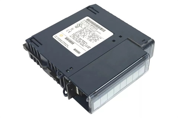
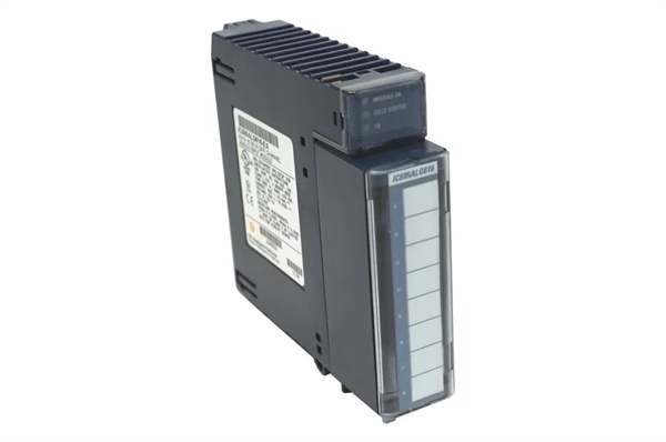
GE IC695ALG616
Field Service Pitfalls: What Rookies Get Wrong
Single-Ended vs Differential MismatchTechnicians configure module for differential mode but wire channels in single-ended configuration, causing measurement errors and ground loop issues.
- Field Rule: Match software configuration to physical wiring. Use differential mode for long cable runs or noisy environments where ground reference differs between signal sources. Use single-ended for short runs (<10 meters) with common ground reference.
Filter Frequency Selection ErrorsEngineers use 500Hz filter with 4-20mA signals from pressure transmitters, reducing resolution to 12 bits and introducing unnecessary noise.
- Field Rule: Select filter based on signal response time and noise environment. Use 8-12Hz for slow process variables (temperature, level, pressure). Use 40-200Hz for fast signals (flow, position). Reserve 500Hz for very fast signals where response time outweighs accuracy.
Ignoring Channel Scanning OptimizationTeams use arbitrary channel numbers (e.g., channels 1-8) for 8-channel applications, requiring all 4 acquisition cycles and slowing scan time.
- Field Rule: For best performance, wire by acquisition cycle groups. For 8 channels: use 1, 2, 5, 6, 9, 10, 13, 14 for fastest scan (all 4 cycles needed anyway but optimal for 16-channel expansion). For 4 channels: use 1, 2, 3, 4 to skip 3 acquisition cycles.
Current Input Wiring Without JumperInstallers connect 4-20mA current input to Channel IN+ and Current Return terminals without jumpering Current Return to Common in single-ended mode.
- Field Rule: In single-ended mode, current inputs require jumper wire between Channel Current Return terminal and Common (COM) terminal. Use shortest possible jumper (<25mΩ resistance) to minimize error. In differential mode, jumper from Channel IN- to Channel Current Return.
Overlooking Open Circuit DetectionProgrammers disable open circuit detection for 4-20mA current inputs to avoid nuisance alarms, missing wire-off faults in safety-critical applications.
- Field Rule: Always enable open circuit detection for 4-20mA loops in critical applications. Configure alarm thresholds appropriately (typically <3.5mA indicates open circuit). Use rate-of-change alarms to differentiate sensor failure from process changes.
Incorrect Scaling ConfigurationDevelopers set High Scale Engineering Units and Low Scale A/D Units incorrectly, causing PLC to read wrong values.
- Field Rule: Verify scaling parameters: High Scale (Eng Units) maps to High Scale (A/D Units); Low Scale (Eng Units) maps to Low Scale (A/D Units). Test calibration by applying known input and verifying PLC reads expected engineering unit value.
Terminal Block IgnoranceTechnicians miss TB LED indication (red = terminal block not present/seated), troubleshooting input issues unnecessarily.
- Field Rule: Check TB LED first when inputs read zero or erratic. Ensure terminal block is fully seated. Use extended terminal blocks (IC694TBB132/IC694TBS132) for shielded cabling applications. The extended shroud provides depth for shield termination.
Alarm Deadband MisconfigurationTeams set alarm deadbands too large, causing alarms to latch even after process returns to normal range.
- Field Rule: Calculate deadband based on process variability and alarm urgency. For high alarms, deadband is range above alarm threshold where alarm remains set. Example: High alarm at 100, deadband of 10 means alarm clears only after value drops below 90. Ensure clear condition remains within engineering unit limits.
Ignoring RF Interference ImpactInstallers mount module near VFDs or radio transmitters without accounting for accuracy degradation (±1.5% of range per spec).
- Field Rule: Maintain distance from high-RF sources (VFDs, radio transmitters, welders). Use shielded cables with proper grounding at module end (connect to ground bar via M3 tap holes). Consider lower filter frequencies (8-12Hz) to reject RF-induced noise.
Rate-of-Change Sampling Rate MisunderstandingProgrammers set rate-of-change sampling rate lower than PLC scan time, causing missed rapid changes.
- Field Rule: Rate-of-change sampling rate (0-300 seconds) determines comparison frequency. Set to 0 for per-sample comparison (fastest detection). For slower processes, set to match typical response time (e.g., 5-10 seconds for temperature changes). Ensure sampling rate is not slower than expected process transient events.
Power Supply InadequacyInstallers add multiple high-current analog modules without checking backplane power budget, causing voltage sag and module failures.
- Field Rule: Calculate total 3.3V and 5.1V current requirements. IC695ALG616 draws 600mA @ 3.3V and 450mA @ 5.1V. Ensure backplane power supply can support sum of all module currents with 20% margin. Upgrade power supply if needed.
Please note: The listed price is for reference only and is not binding. Final pricing and terms are subject to negotiation based on current market conditions and availability.


