
Description
Hard-Numbers: Technical Specifications
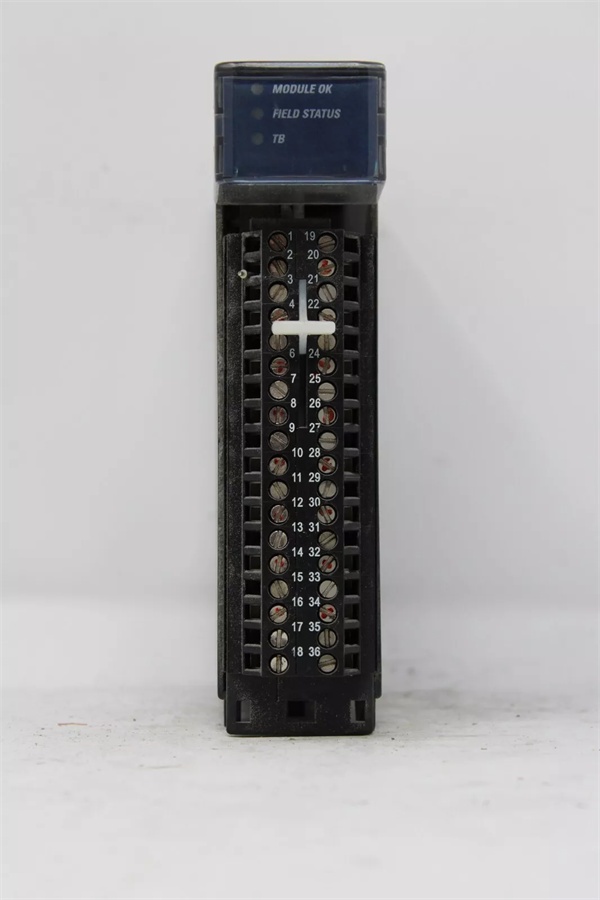
- Channel Configuration: 8 single-ended or 4 differential input channels .
- Voltage Input Ranges: ±10 VDC, 0-10 VDC, ±5 VDC, 0-5 VDC, 1-5 VDC .
- Current Input Ranges: 0-20 mA, 4-20 mA, ±20 mA .
- ADC Resolution: 24-bit sigma-delta converter .
- Data Format: Integer or 32-bit IEEE floating-point .
- Configurable Input Filter: 6 selectable frequencies (8 Hz, 12 Hz, 16 Hz, 40 Hz, 200 Hz, 500 Hz) per channel .
- Isolation Rating: Non-isolated – all channels share a common reference .
- Operating Temperature: 0°C to +60°C (standard industrial range).
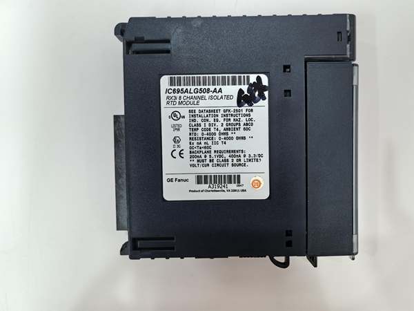
- Backplane Current: 5V @ 600mA max; 3.3V @ 450mA max .
- Required Firmware: RX3i CPU firmware 3.0 or later; Proficy Machine Edition 5.0 SP3 or later .
- Required Terminal Block: IC694TBB032 (Box), IC694TBB132 (Extended Box), IC694TBS032 (Spring), or IC694TBS132 (Extended Spring) .
GE IC695ALG600
The Real-World Problem It Solves
Isolated input cards cost more and consume more real estate. For a control panel where all your 4-20mA transmitters and 0-10V potentiometers are powered from the same 24VDC supply and share a common ground, paying for channel-to-channel isolation is wasted money and panel space.
Where you’ll typically find it:
- Machine Control Panels: Reading multiple motor speed references (0-10V) and analog feedback signals from drives within the same cabinet.
- Batching Systems: Monitoring weigh scale load cells (mV/V) and valve position feedback (4-20mA) where all sensors are locally powered.
- Test Stands & Lab Rigs: Where signal sources are bench power supplies and data acquisition is from a controlled, single-ground environment.
It’s the workhorse for cost-effective analog acquisition when your signal sources already share a clean, common ground.
Hardware Architecture & Under-the-Hood Logic
This is a non-isolated module, meaning all eight channels reference the same common ground point on the backplane. The front-end uses programmable gain amplifiers and multiplexers to route each channel’s signal to a high-resolution 24-bit sigma-delta ADC . The configuration for single-ended vs. differential is done in software, which internally switches the multiplexer paths.
- Input Multiplexing & Conditioning: Based on the channel’s software configuration (voltage/current, range), internal solid-state switches connect the input to the appropriate scaling network. A current input is routed through a precision shunt resistor to convert mA to a measurable voltage .
- Differential vs. Single-Ended Routing: When configured for differential input, the module uses two physical terminals per channel to measure the voltage difference between them, rejecting common-mode noise. In single-ended mode, each channel measures the voltage between its terminal and the common ground .
- Sigma-Delta Conversion & Filtering: The conditioned signal is digitized by the 24-bit ADC. A user-selectable digital filter (8Hz to 500Hz) is then applied to smooth the reading and reject out-of-band noise .
- Diagnostics & Data Handling: The module performs continuous diagnostics: open-circuit detection for 4-20mA loops (by monitoring for a near-zero mA reading), over-range/under-range checks, and module health monitoring. Scaled data and status bits are sent to the CPU .
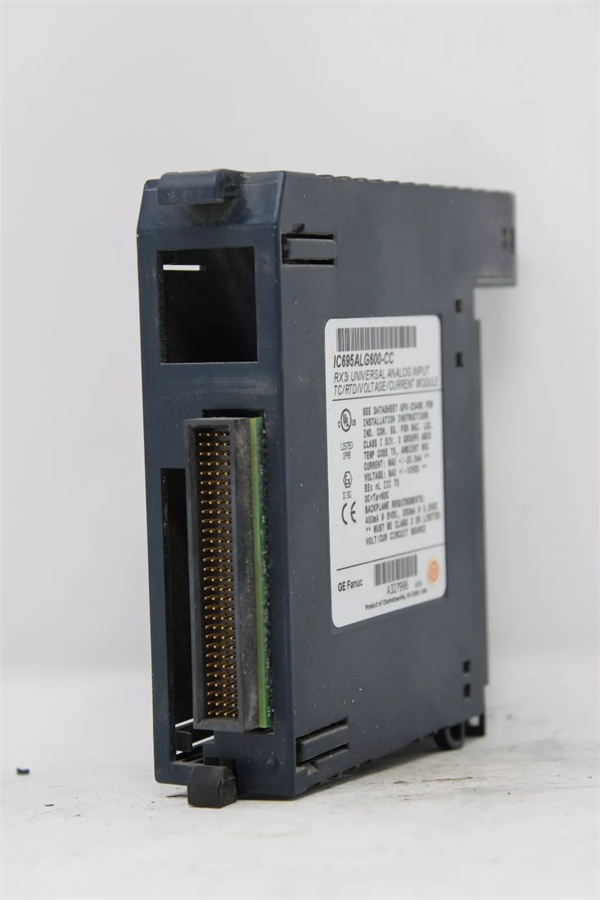
GE IC695ALG600
Field Service Pitfalls: What Rookies Get Wrong
Creating Ground Loops with Single-Ended Wiring
The biggest trap with non-isolated modules. You wire a 4-20mA transmitter located 100 feet away, grounding its negative wire at the sensor and again at the module’s common terminal. This creates a ground loop—stray currents flow through the signal wire, adding offset or noise to your reading.
- Field Rule: Establish a single-point ground for the entire analog loop. Typically, ground the shield and the signal common at the module end only. Leave the field device floating if possible. Use a differential input configuration for long wire runs in noisy environments.
Using Differential Mode Unnecessarily
A rookie sees “differential” and thinks it’s always better, configuring all channels as differential. This cuts your available channels from 8 to 4. For signals sourced within the same cabinet (like a local potentiometer), single-ended mode is perfectly adequate and doubles your point count.
- Quick Fix: Reserve differential mode for long wire runs (>50 ft) or electrically noisy environments. Use single-ended mode for short, local signals to maximize your I/O density. Document the wiring scheme in the panel drawing.
Ignoring the Common-Mode Voltage Limit
Because the module is non-isolated, all input voltages are referenced to the backplane ground. If you connect a signal whose negative lead is at a different ground potential (e.g., a device powered from a separate, noisy supply), you can exceed the common-mode voltage range, saturate the input amplifier, and get garbage data.
- Field Rule: Verify all field devices share the same power supply ground or are within the module’s specified common-mode voltage range. If in doubt, measure the voltage between the field device’s negative terminal and the module’s common terminal with a multimeter before connecting. A reading more than a few volts indicates a ground potential difference problem.
Commercial Availability & Pricing Note
Please note: The listed price is for reference only and is not binding. Final pricing and terms are subject to negotiation based on current market conditions and availability.


