
Description
Hard-Numbers: Technical Specifications
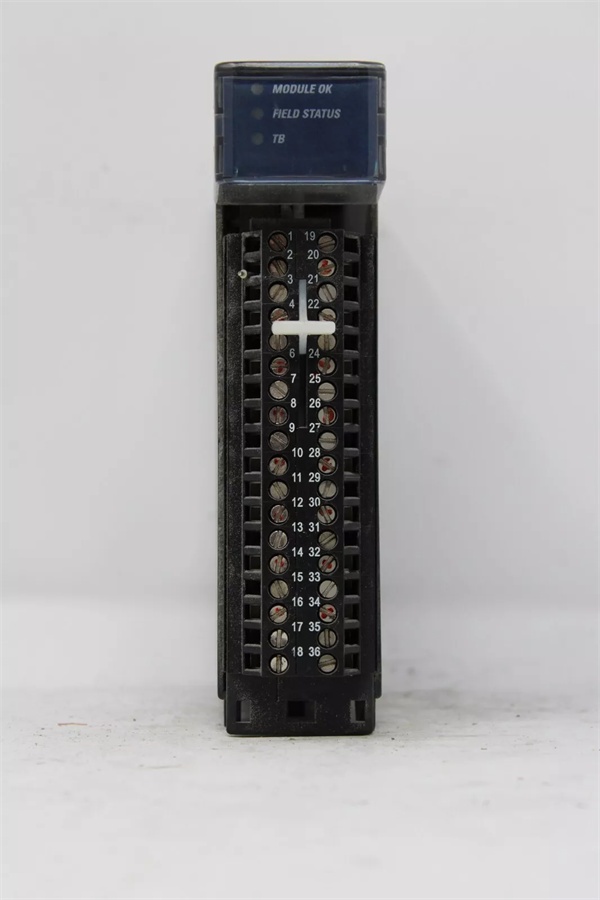
- Channel Count: 8 universal input channels, arranged in two groups of four .
- Supported Signal Types: Voltage (±50mV, ±150mV, 0-5V, 1-5V, 0-10V, ±10V), Current (0-20mA, 4-20mA, ±20mA), Thermocouple (B, C, E, J, K, N, R, S, T), RTD (Pt, Ni, NiFe, Cu), Resistance (0-4000 Ω) .
- Cold Junction Compensation: 2 dedicated CJC channels for thermocouple inputs .
- Resolution: Up to 16-bit (sigma-delta ADC) .
- Configurable Input Filter: 6 selectable frequencies (8 Hz, 12 Hz, 16 Hz, 40 Hz, 200 Hz, 1000 Hz), per channel .
- Isolation Rating: Channel-to-backplane and channel-to-channel isolation .
- Operating Temperature: 0°C to +60°C .
- Power Dissipation: 5.4W max .
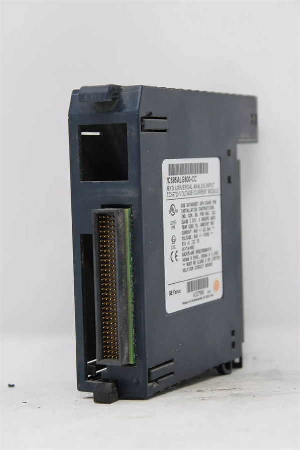
- Backplane Current: 5V @ 400mA max; 3.3V @ 350mA max .
- Hot-Swap: Supports Removal and Insertion Under Power (RIUP) .
- Required Firmware: RX3i CPU firmware 2.80 or later; Proficy Machine Edition 5.0 SP1A or later .
GE IC695ALG600
The Real-World Problem It Solves
Plant floors are littered with dedicated cards for 4-20mA, thermocouples, and RTDs, eating up slots and complicating spares management. This module kills that clutter. It’s a single-slot solution for a control panel that monitors pump pressure (4-20mA), reactor temperature (Type J T/C), tank level (4-20mA), and bearing temp (Pt100 RTD).
Where you’ll typically find it:
- Compact Skid-Mounted Systems: In packaged water treatment or compressor skids where panel space is tight and signals are mixed.
- Legacy System Upgrades: Replacing three old, failing single-purpose cards (analog in, T/C, RTD) with one modern, software-configured module.
- Batch Process Lines: Where a single station needs to read pressure transmitters, valve positioners (0-10V), and multiple temperature points from different sensor types.
It turns a cabinet full of specialized hardware into a software configuration exercise.
Hardware Architecture & Under-the-Hood Logic
This is a smart module with its own microprocessor for signal conditioning and backplane comms. The eight channels are divided into two isolated groups of four. The magic is in the front-end: programmable gain amplifiers and multiplexers route each channel’s signal to the correct conditioning path before the ADC.
- Signal Routing & Conditioning: Based on the channel’s software configuration, internal relays connect the input to the appropriate circuit—a precision current shunt for mA, a high-impedance buffer for voltage, or a current source for RTD/resistance .
- Cold Junction Compensation: The two dedicated CJC sensors measure the temperature at the terminal block where thermocouple wires land. The module’s firmware uses this reading to compensate for the “cold junction” error, critical for T/C accuracy .
- Sigma-Delta Conversion & Filtering: A high-resolution sigma-delta ADC digitizes the conditioned signal. One of six hardware filter frequencies is applied per channel to match the signal’s speed and noise environment (e.g., 8 Hz for slow temperature, 1000 Hz for fast vibration) .
- Linearization & Scaling: For thermocouples and RTDs, the digitized value is linearized using ITS-90 standard tables. For all types, the value is then scaled to the configured engineering units (PSI, °C, %, etc.) .
- Diagnostics & Data Transfer: The module continuously performs open-wire detection (for 4-20mA loops), over/under-range checks, and calibration verification. Processed data and status are packetized for the CPU .
GE IC695ALG600
Field Service Pitfalls: What Rookies Get Wrong
Neglecting Cold Junction Compensation for Thermocouples
You wire in a Type K thermocouple, configure the channel in PME, but get a reading 20°C off ambient. The rookie blames the sensor. The veteran checks if the CJC channel is assigned and enabled in the hardware configuration for the T/C group.
- Field Rule: For any thermocouple input, verify the associated CJC channel is configured and its sensor is functional. The CJC reading should roughly match the cabinet’s internal temperature. If it reads -40°C or +85°C, the CJC sensor is faulty or disconnected.
Mismatching Filter Frequency to Process Dynamics
Configuring a 1000 Hz filter on a tank level signal (which changes over minutes) seems harmless. It isn’t. The fast filter lets high-frequency electrical noise through, causing the level reading to jitter and triggering false alarms.
- Quick Fix: Match the filter to the process. Use 8-16 Hz for slow processes (temperature, level), 40 Hz for medium (pressure, flow), and 200-1000 Hz only for very fast signals (vibration). Start with a slower filter and tighten only if needed.
Using Voltage Inputs for Long Wire Runs Without Shielding
Running a 0-10V signal from a remote sensor 200 feet on unshielded twisted pair. The voltage drop across the wire resistance causes a low reading, and induced noise makes it unstable.
- Field Rule: For long-distance analog voltage signals (>50 ft), use a 4-20mA transmitter instead. Current loops are immune to voltage drop. If you must use voltage, employ shielded cable, ground the shield at the module end only, and consider a signal conditioner at the source.
Commercial Availability & Pricing Note
Please note: The listed price is for reference only and is not binding. Final pricing and terms are subject to negotiation based on current market conditions and availability.


