
Description
Hard-Numbers: Technical Specifications
| Parameter | Specification |
|---|---|
| Number of Channels | 8 isolated differential inputs |
| RTD Input Types | Platinum 385 (50, 100, 200, 500, 1000Ω), Platinum 391.6 (50, 100, 200, 500, 1000Ω), Nickel 618 (100, 200, 500, 1000Ω), Nickel 672 (120Ω), Nickel-Iron 518 (604Ω), Copper 426 (10, 50, 100Ω) |
| Resistance Input Ranges | 0-260, 0-525, 0-1050, 0-2100, 0-3150, 0-4200 ohms |
| Maximum RTD Lead Resistance | 25Ω each side (50Ω total) |
| Excitation Current | 0.238-1.654 mA (depends on input type) |
| Temperature Ranges | Platinum 385: -200 to +850°C; Platinum 391.6: -200 to +630°C; Nickel 618/672: -100 to +260°C; Nickel-Iron 518: -100 to +200°C; Copper 426: -100 to +260°C |
| Temperature Accuracy (4-wire) | Pt100 @ 25°C: ±0.7°C (typical), ±1.2°C (maximum over temp span) |
| Temperature Accuracy (1000Ω) | Pt1000 @ 25°C: ±0.5°C (typical), ±0.9°C (maximum over temp span) |
| Resistance Accuracy | 250Ω: ±0.25Ω; 500Ω: ±0.3Ω; 1000Ω: ±0.5Ω; 2000Ω: ±0.9Ω; 3000Ω: ±1.3Ω; 4000Ω: ±1.7Ω |
| Repeatability | 0.05% of span at constant temperature over 30-second period (0.1% for 10-ohm copper, 28Hz filter) |
| Channel Update Rate | 120ms for all 8 channels |
| Notch Filters | 2.3 Hz, 4 Hz, 4.7 Hz, 24 Hz, 28 Hz (selectable per channel) |
| Normal Mode Noise Rejection | 2.3 Hz filter @ 50/60Hz: 67dB; 4 Hz filter @ 50Hz: 67dB, @ 60Hz: 80dB; 4.7 Hz filter @ 50/60Hz: 80dB; 24 Hz filter @ 50/60Hz: 25dB; 28 Hz filter @ 50/60Hz: 100dB |
| Common Mode Rejection | > 70dB (2/3-wire), > 90dB (4-wire), > 100dB (resistance inputs) |
| Channel-to-Channel Crosstalk | -70dB minimum |
| Data Format | 16-bit integer (in 32-bit field) or 32-bit IEEE floating point |
| Measurement Units | Degrees Celsius, Degrees Fahrenheit, or Ohms (selectable) |
| Diagnostics | Over Range, Under Range, High/Low Alarm, High-High/Low-Low Alarm, Open Circuit Detection, Positive/Negative Rate of Change Alarm, Watchdog, RAM Fail, Flash Fail |
| Fault Reporting | Configurable enable/disable for each alarm type |
| Channel Behavior on Fault | Default to 0 or Hold Last State (configurable) |
| Isolation (Field to Backplane) | 250VAC continuous; 1500VAC for 1 minute; 2550VDC for 1 second |
| Channel-to-Channel Isolation | Supported |
| Power Consumption | 3.3V: 400mA; 5.1V: 200mA |
| Power Dissipation | 2.5W maximum |
| Terminal Blocks | Box-style (IC694TBB032), Extended Box-style (IC694TBB132), Spring-style (IC694TBS032), Extended Spring-style (IC694TBS132) – sold separately |
| LED Indicators | Module OK, Field Status |
| Hot-Swap | Supported (per RX3i System Manual) |
| CPU Compatibility | RX3i Universal Backplane; Firmware version 5.5 or later required; Machine Edition version 5.8 or later for configuration |
| Operating Temperature | 0°C to 60°C |
| Storage Temperature | -40°C to 85°C |
| Humidity | 5% to 95% non-condensing |
| Weight | 0.56 lbs (0.26 kg) |
| Dimensions | 145mm x 140mm x 34mm (5.71″ x 5.51″ x 1.34″) |
| Approvals | UL, UL HAZLOC, CE, ATEX C1D2, ABS, BV, DNV, GL, KRS, LR |
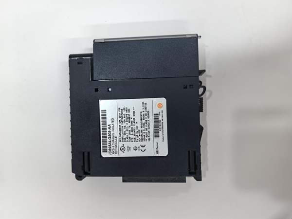
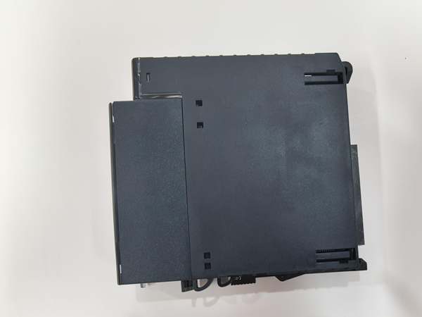
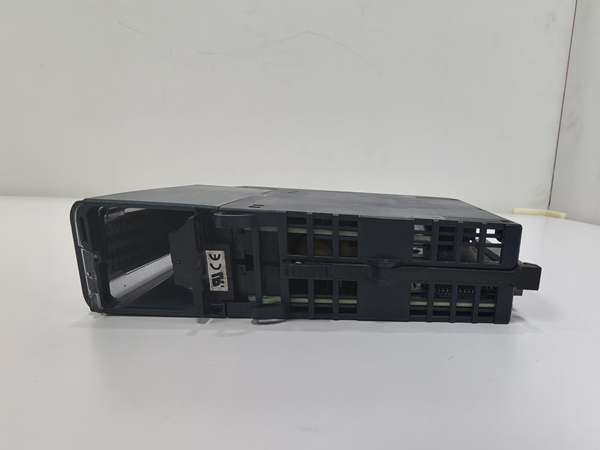
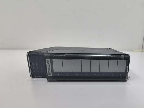
GE IC695ALG508
The Real-World Problem It Solves
This module provides direct RTD sensor interfacing with high-accuracy temperature measurement, eliminating need for external signal transmitters and reducing installation cost. Its ITS-90 linearization, open circuit detection, and rate-of-change alarms enable predictive maintenance and early fault detection in critical temperature control loops.
Where you’ll typically find it:
- Chemical processing plants monitoring reactor vessel temperatures and heat exchanger performance
- Food & beverage production tracking oven, freezer, and pasteurization temperatures
- Pharmaceutical manufacturing validating sterilization and fermentation temperature profiles
- Power generation monitoring steam turbine and generator cooling system temperatures
Bottom line: It’s your precision RTD input solution for mission-critical temperature measurement applications requiring high accuracy, comprehensive diagnostics, and direct sensor connectivity.
Hardware Architecture & Under-the-Hood Logic
The IC695ALG508 contains 8 isolated differential input circuits with individual ADCs, excitation current sources, and programmable notch filters. Each channel supports 2-wire, 3-wire, and 4-wire RTD configurations, with automatic lead resistance compensation for 3-wire sensors. The module implements ITS-90 standard linearization for Platinum RTDs.
Signal flow breakdown:
- RTD sensor (Pt100, Pt1000, Ni, Cu, etc.) connected via terminal block (2/3/4-wire)
- Module applies precision excitation current (0.238-1.654 mA depending on sensor type)
- Differential input measures voltage across RTD (compensating for lead resistance in 3/4-wire mode)
- Programmable notch filter (2.3-28Hz) removes electrical noise and interference
- ADC converts filtered analog signal to digital value
- CPU applies ITS-90 linearization algorithm based on RTD type
- Linearized temperature stored in dual-port memory (16-bit integer or 32-bit float)
- PLC CPU reads temperature during scan cycle via backplane
- Diagnostics circuitry monitors for open circuit (wire-off), over/under range, rate of change
- Alarm status bits updated for enabled diagnostic conditions
- LED drivers illuminate Module OK and Field Status indicators
- Fault configuration (default 0 vs hold last state) applied when fault detected
RTD type and excitation current mapping:
- Platinum 385 (50Ω): 1.175 mA
- Platinum 385 (100, 200, 500, 1000Ω): 0.717 mA
- Platinum 391.6 (50Ω): 1.175 mA
- Platinum 391.6 (100, 200Ω): 0.717 mA
- Platinum 391.6 (500, 1000Ω): 0.238 mA
- Nickel 618 (100, 200Ω): 0.717 mA
- Nickel 618 (500, 1000Ω): 0.238 mA
- Nickel 672 (120Ω): 0.717 mA
- Nickel-Iron 518 (604Ω): 0.238 mA
- Copper 426 (10Ω): 1.654 mA
- Copper 426 (50, 100Ω): 1.175 mA
Lead resistance compensation (3-wire mode):
- Module switches to measure lead resistance every 100 samples
- Measured lead resistance used to compensate next 100 samples
- Automatic compensation eliminates lead wire error (up to 25Ω per side)

GE IC695ALG508
Field Service Pitfalls: What Rookies Get Wrong
2-Wire vs 3-Wire vs 4-Wire ConfusionTechnicians wire 3-wire RTDs as 2-wire connections, losing lead resistance compensation and introducing measurement errors in long cable runs.
- Field Rule: Always use 3-wire or 4-wire for Pt100 sensors with cable runs > 2 meters. 4-wire provides best accuracy (compensates both lead resistances). 2-wire only for short runs (<1 meter) where lead resistance is negligible.
Mixing RTD StandardsEngineers configure Pt100 385 sensors as Pt100 391.6 in software, causing significant temperature reading errors (~0.4°C at 100°C).
- Field Rule: Verify RTD standard stamped on sensor housing (α = 0.00385 vs α = 0.003916). Match software configuration to sensor type exactly. Check sensor datasheet for IEC 751 vs JIS 1604 standard compliance.
Ignoring Notch Filter SelectionInstallers leave default 2.3 Hz filter in 50Hz/60Hz electrical environments, causing unstable readings from power line interference.
- Field Rule: Select notch filter based on environment: 2.3 Hz for DC environments, 4-4.7 Hz for 50Hz power, 24 Hz for 60Hz power, 28 Hz for both frequencies. Use higher filter (24-28Hz) if readings drift with nearby VFDs or motors.
Exceeding Lead Resistance LimitTeams install RTDs with long cable runs exceeding 25Ω per side, causing measurement saturation or open circuit faults.
- Field Rule: Calculate total lead resistance: wire resistance per meter × cable length (both directions). For 3-wire, add both lead resistances. Maximum 25Ω per side (50Ω total). Use 4-wire or larger resistance RTDs (Pt1000) for long cable runs.
Rate-of-Change Alarm MisconfigurationProgrammers set aggressive rate-of-change thresholds without considering thermal lag, causing nuisance alarms during normal process temperature changes.
- Field Rule: Configure rate-of-change alarm based on process thermal mass and response time. For large thermal mass (reactors, vessels), use 1-5°C/min. For fast response (heat exchangers), use 5-10°C/min. Test alarms during commissioning.
Incorrect Fault Behavior ConfigurationTechs configure channels to “Hold Last State” in safety-critical applications, potentially maintaining unsafe temperatures during sensor failure.
- Field Rule: Use “Hold Last State” only for non-critical monitoring or redundant systems. Configure safety-critical temperature channels to “Default to 0” (or safe fail-safe value) on fault detection to trigger safe shutdown.
Missing Terminal Block ShroudInstallers use standard terminal blocks instead of extended versions for shielded RTD cabling, compromising EMI protection.
- Field Rule: Use Extended Box-style (IC694TBB132) or Extended Spring-style (IC694TBS032) for shielded cable installations. Extended blocks provide extra shroud depth for proper shield termination. Standard blocks (IC694TBB032/TBS032) only for unshielded wiring.
Overlooking 3-Wire Compensation EnablementEngineers configure 3-wire RTDs but leave periodic lead resistance measurement disabled, sacrificing accuracy.
- Field Rule: Always enable “Periodic Lead Resistance Compensation” for 3-wire RTDs in configuration software. Module automatically measures lead resistance every 100 samples and compensates for next 100 cycles. This eliminates lead resistance drift due to temperature changes.
RTD Type vs Resistance Input ConfusionNew techs configure RTD type but sensor is actually a generic resistance device (potentiometer, thermistor), causing inaccurate readings.
- Field Rule: Verify sensor type before configuration. RTD sensors are metallic (Pt, Ni, Cu) with predictable resistance-temperature curves. Thermistors are semiconductor devices with exponential curves. Use “Resistance Input” mode for generic resistance measurement (0-4200Ω ranges).
Incorrect Wire Gauge SelectionInstallers use 22AWG wire for Pt100 sensors with long runs, causing excessive lead resistance and measurement error.
- Field Rule: Calculate acceptable lead resistance based on accuracy requirement. For Pt100 (0.1°C accuracy), total lead resistance must be < 0.4Ω. Use 18AWG or 16AWG for runs > 10 meters. Wire gauge must be consistent for all 3-wire connections to ensure proper compensation.
Ignoring Field Status LEDMaintenance staff overlook Field Status LED indication, missing critical external 24VDC power supply warnings.
- Field Rule: Monitor both Module OK (green = good) and Field Status LEDs. Field Status LED indicates external 24VDC supply status and fault presence. If Field Status LED is off or red, check external 24VDC supply voltage and connections before troubleshooting individual channels.
CPU Firmware IncompatibilityTeams install IC695ALG508 with older RX3i CPU firmware (< 5.5), causing module recognition failures and communication errors.
- Field Rule: Verify RX3i CPU firmware version is 5.5 or later before installing IC695ALG508. Upgrade CPU firmware if necessary. Use Proficy Machine Edition version 5.8 or later for module configuration. Incompatible with Series 90-30 PLC CPUs.
Please note: The listed price is for reference only and is not binding. Final pricing and terms are subject to negotiation based on current market conditions and availability.


