
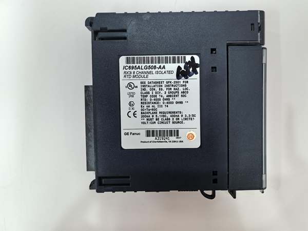
Description
Hard-Numbers: Technical Specifications
- Channel Count: 8 isolated differential input channels.
- Supported RTD Types: Platinum (Pt 385, Pt 391.6), Nickel (Ni 618, Ni 672), Copper (Cu 426), Nickel-Iron (NiFe 518) .
- Resistance Input Range: 0–260, 0–525, 0–1050, 0–2100, 0–3150, 0–4200 ohms (corresponding to 250, 500, 1000, 2000, 3000, 4000 ohm spans) .
- Wiring Configuration: 2, 3, or 4-wire, configurable per channel .
- Data Format: 32-bit IEEE floating-point or 16-bit integer (in a 32-bit field), selectable per channel .
- Configurable Notch Filter: 2.3 Hz to 28 Hz, programmable per channel for power-line noise rejection .
- Isolation Rating: Channel-to-channel and channel-to-ground isolation.
- Operating Temperature: 0°C to +60°C .
- Power Dissipation: 2.5W max .
- Backplane Current: 3.3V @ 400mA; 5V @ 200mA .
- Hot-Swap: Supports Removal and Insertion Under Power (RIUP) .
- Required Terminal Block: IC694TBB032 (Box-style), IC694TBS032 (Spring-style), or extended versions; ordered separately .
GE IC695ALG508
The Real-World Problem It Solves
Using a traditional 4-20mA temperature transmitter for every RTD adds cost, wiring complexity, and a failure point. It also introduces conversion error and lag. This module cuts out the middleman, letting the PLC backplane read the RTD’s resistance directly.
Where you’ll typically find it:
- Reactor Vessel Monitoring: Directly connecting multiple Pt100 RTDs to monitor jacket and internal temperatures in chemical or pharmaceutical batch processes.
- Turbine & Compressor Bearing Protection: Measuring bearing and winding temperatures with high-stability RTDs in power generation or offshore platforms.
- Precision Process Control: In food sterilization or semiconductor furnaces where direct sensor connection ensures fast response and accurate temperature profiling.
It replaces a rack of single-purpose signal conditioners with one high-density, software-configurable module.
Hardware Architecture & Under-the-Hoard Logic
This isn’t a simple resistor reader; it’s a bank of eight independent, isolated measurement circuits with a dedicated microprocessor for signal processing and backplane communication. Each channel is a complete measurement chain.
- Programmable Excitation & Measurement: The module applies a precise, programmable constant current to the RTD. A high-impedance differential amplifier then measures the voltage drop across the sensor .
- Lead Resistance Compensation: For 3-wire RTDs, the module periodically (e.g., every 100 samples) measures the resistance of one lead wire. It uses this value to mathematically subtract the lead resistance error from the total measurement, a critical step for long cable runs .
- Sigma-Delta ADC & Digital Filtering: The analog voltage is converted by a high-resolution sigma-delta ADC. A programmable digital notch filter then removes specific power-line frequencies (50/60 Hz) to clean up the signal .
- Linearization & Scaling: The digitized resistance value is linearized according to the ITS-90 international temperature standard for the specific RTD type (e.g., Pt100). The result is scaled to engineering units (°C, °F, or Ω) .
- Diagnostics & Data Packaging: The module runs continuous diagnostics for open wires, shorts, and over-range conditions. Processed data and status bits are packetized and sent to the CPU over the high-speed RX3i backplane .
GE IC695ALG508
Field Service Pitfalls: What Rookies Get Wrong
Mismatching Physical Wiring and Software Configuration
The most common call-out: someone wires a 3-wire RTD but leaves the channel configured for “2-Wire” in Proficy Machine Edition. The module won’t perform lead resistance compensation, baking the resistance of hundreds of feet of wire into the temperature reading.
- Field Rule: Before power-up, create a physical I/O checklist. Walk the wires and verify the Wiring Configuration parameter for each channel (2/3/4-Wire) matches the actual sensor termination at the module’s terminal block.
Leaving Lead Resistance Compensation Disabled
For 3-wire RTDs, the “Periodic Lead Resistance Compensation” function might be disabled by default in the channel’s advanced parameters. If it’s off, you’re not getting the accuracy you paid for.
- Quick Fix: In the hardware configuration, drill into each 3-wire RTD channel’s settings. Find the lead resistance compensation control and explicitly set it to “Enabled” .
Poor Shielding and Grounding Practices
The module has no dedicated shield terminals. Rookies tie cable shields to a random ground point or ground both ends, creating a ground loop that injects 60Hz hum into the low-level mV signal.
- Field Rule: Land all cable shields on the dedicated ground bar running along the bottom of the RX3i backplane. Ground the shield at the module end only. Keep the sensor end of the shield insulated and floating .
Commercial Availability & Pricing Note
Please note: The listed price is for reference only and is not binding. Final pricing and terms are subject to negotiation based on current market conditions and availability.


