
Description
Hard-Numbers: Technical Specifications
- Channel Count: 16 single-ended (configurable as 8 differential) .
- Signal Types: Voltage (±10V, ±5V, 0-10V, 0-5V); Current (4-20mA, 0-20mA with external 250Ω resistor); RTD (PT100/PT1000, 2/3/4-wire); Thermocouple (J, K, T, E, R, S, B, N, C types) .
- Resolution: 16-bit ADC (±0.05% of full-scale accuracy) .
- Sampling Rate: 2 kHz per channel (single-channel mode); ≥250 Hz per channel (all-channel scanning) .
- Isolation Rating: 3000 VDC channel-to-channel; 2500 VDC channel-to-ground .
- Input Impedance: ≥10 MΩ (voltage); 250 Ω (current, built-in); 10 kΩ (RTD) .
- Cold Junction Compensation: Integrated, ±0.5°C accuracy for thermocouples .
- Operating Temperature: -40°C to +85°C .
- Vibration/Shock: 5G (5-500 Hz) per IEC 60068-2-6; 100G (6ms half-sine) per IEC 60068-2-27 .
- Enclosure Rating: IP20 (module); can achieve IP67 with RX7i rack and optional cover .
- Communication: RX3i/RX7i backplane bus, supports hot-swap and redundant configuration .
- Dimensions/Weight: 114mm (H) × 140mm (D) × 40mm (W); approx. 320g .
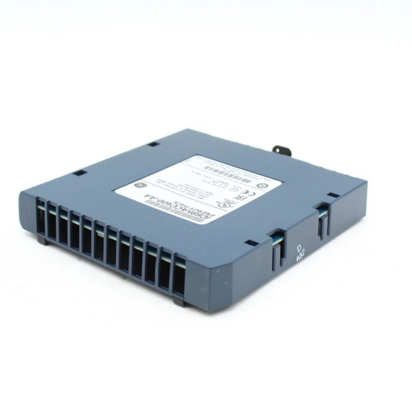
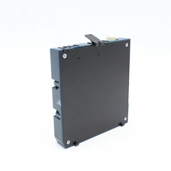
GE IC695ACC400
The Real-World Problem It Solves
Running separate wires for dozens of thermocouples and 4-20mA transmitters to individual cards wastes cabinet space, increases wiring complexity, and creates a maintenance nightmare for ground loops. This module consolidates up to 16 mixed signals into one slot with fortress-grade isolation between each channel.
Where you’ll typically find it:
- Furnace and Kiln Control: Monitoring multiple zone temperatures (Type K thermocouples) and fuel flow rates (4-20mA) in cement or metal heat treatment plants.
- Reactor Vessel Monitoring: Tracking jacket temperature (RTD), internal pressure (4-20mA), and cooling water flow (0-10V) in batch chemical or pharmaceutical processes.
- Turbine and Compressor Monitoring: Measuring bearing temperatures (thermocouple), vibration (4-20mA), and lube oil pressure (0-5V) in power generation or offshore platforms.
It replaces a rack of single-purpose cards with one intelligent, mixed-signal module that laughs at electrical noise.
Hardware Architecture & Under-the-Hood Logic
This isn’t a simple multiplexer; it’s a bank of 16 independent, isolated signal conditioners and ADCs sharing a backplane interface. Each channel has its own dedicated isolation barrier and programmable gain amplifier.
- Per-Channel Signal Conditioning: Each input channel passes through a programmable front-end. For voltage, it’s a high-impedance buffer. For current, it routes through a precision 250Ω shunt. For thermocouples/RTDs, it provides excitation current and cold-junction compensation .
- Isolation Barrier: The conditioned analog signal crosses a 3000VDC isolation barrier (typically optical or magnetic) to the measurement side. This breaks ground loops and protects the backplane from field-side transients .
- Analog-to-Digital Conversion: The isolated signal is digitized by a high-speed, 16-bit successive approximation register (SAR) ADC. The module can sequence through all channels or focus on a single channel at 2kHz .
- Data Processing & Diagnostics: The digital values are linearized (for T/C and RTD), filtered, and checked against user-configured alarms (open wire, over/under range, rate-of-change). Processed data and status are packetized for the backplane .
- Backplane Communication: A dedicated ASIC manages the high-speed serial communication with the CPU over the RX3i backplane, handling data transfer, module configuration, and diagnostic reporting .
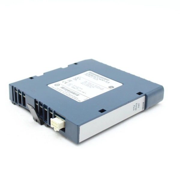
GE IC695ACC400
Field Service Pitfalls: What Rookies Get Wrong
Skipping the Shield Ground at One End Only
Rookies tie shield drains from all 16 channels to the module’s terminal and also ground them at the sensor end, creating a ground loop that injects 50/60Hz hum into your milliamp signals.
- Field Rule: Ground the shield at the module end only. Leave the sensor end of the shield insulated and floating. Use a dedicated shield bar in the cabinet, bonded to the chassis ground, not the logic ground.
Mismatching Input Type and Sensor in Software
You wire a 4-20mA pressure transmitter but leave the channel configured for ±10V in the Proficy Machine Edition hardware configuration. The module’s internal 250Ω shunt isn’t engaged, so you read garbage.
- Quick Fix: Before power-up, print the I/O configuration sheet. Physically walk the wires and verify each channel’s Hardware Configuration (e.g., 4-20mA, Type K, PT100) matches the sensor on the other end. A mismatch can damage the module.
Ignoring the Cold Junction Compensation (CJC) Sensor
For thermocouple measurements, the module’s terminal block has an internal CJC sensor. If you mount the module right next to a hot power supply or in direct sunlight, the CJC reading is wrong, skewing all temperature readings by the ambient error.
- Field Rule: Ensure the module is mounted in a location representative of the ambient temperature at the terminal block. Keep it away from heat sources. For critical measurements, use an external, high-accuracy CJC module referenced to an ice bath.
Assuming All Channels are Created Equal for RTDs
You wire a 3-wire PT100 to a channel configured for 2-wire. The module can’t compensate for lead resistance, introducing an error proportional to your wire run length.
- Field Rule: Match the RTD wiring configuration in the software (2, 3, or 4-wire) to the physical sensor wiring. For runs over 50 feet, always use 3-wire or 4-wire to cancel lead resistance.
Please note: The listed price is for reference only and is not binding. Final pricing and terms are subject to negotiation based on current market conditions and availability.


