
Description
Hard-Numbers: Technical Specifications
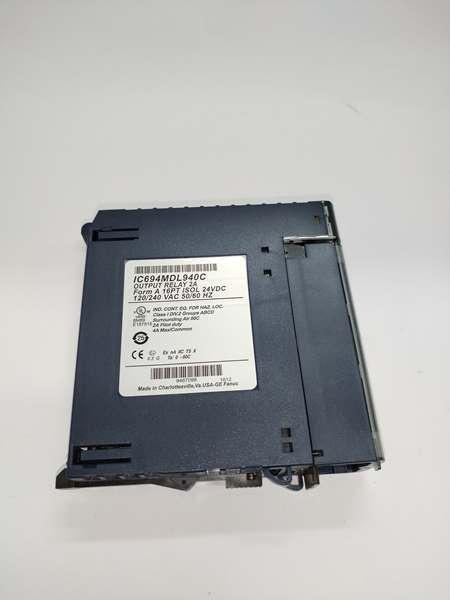
- Output Points: 16 Form A (Normally Open) relay contacts, organized in 4 groups of 4 outputs each
- Rated Voltage: 24VDC, 120/240VAC (nominal)
- Operating Voltage Range: 5–30VDC, 5–250VAC (47–63Hz)
- Output Current: 10mA minimum per point; 2A maximum pilot duty per output; 4A maximum per group common; 16A maximum per module
- Maximum Inrush: 5A
- Isolation Rating: 250VAC continuous (field to backplane, point to point); 1500VAC for 1 minute (dielectric withstand)
- Response Time: 15ms maximum (on/off)
- Backplane Power Draw: 7mA @ 5VDC + 135mA @ 24V relay bus (all outputs ON)
- Operating Temperature: 0°C to 60°C (+32°F to +140°F)
- Contact Life: 300,000 operations at 2A/24–120VAC (resistive); 150,000 at 2A/240VAC; 100,000 at 2A/24VDC; up to 1,000,000 at 0.1A
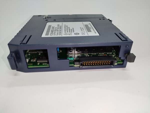
- Terminal Block: Integrated 20-screw terminal block (included with module)
- Hot Swap: Not supported—module must not be inserted or removed under power
- Fuses: None—external fusing recommended for load protection
IC694MDL940
The Real-World Problem It Solves
When you’re controlling 16 indicator lamps, small solenoid valves, or low-current contactor coils from a single I/O slot, you don’t need point-to-point isolation—you need density and simplified wiring. The MDL940 delivers 16 outputs in a single-slot module with only 4 common terminals instead of 16 individual returns. This cuts your terminal block wiring in half and saves rack space compared to running two 8-point modules.
Where you’ll typically find it:
- Control panels with high-density discrete outputs (pump station annunciator panels, motor status indication banks) where all loads share the same voltage source
- Packaged machinery (conveyor systems, packaging lines) with multiple 24VDC solenoid valves and indicator lights on a common 24VDC supply
- Retrofit projects upgrading from older relay-based control to PLC control, where grouped commons match the original relay board wiring scheme
Bottom line: It’s the high-density relay module for low-current, common-voltage applications. If all your loads run on the same power source, grouped commons save wiring time and terminal space.
Hardware Architecture & Under-the-Hood Logic
The MDL940 is a passive relay module with no onboard microprocessor. It receives 16 discrete output commands from the host CPU (RX3i or Series 90-30) over the backplane bus and energizes or de-energizes 16 electromechanical relay coils. Each relay is a Form A (SPST-NO) contact, but unlike the MDL916 and MDL930, the outputs are not individually isolated. Instead, they’re organized into 4 groups of 4 outputs each, with each group sharing a common return terminal.
Internal signal path:
- CPU command → Backplane bus → Module interface latches 16 output bits
- Driver circuit → Energizes relay coils individually → Relays close their Form A contacts
- Field power → External AC/DC source → Through closed relay contact → Load → Group common terminal
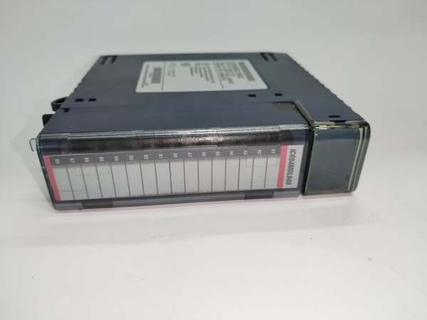
- LED status → 16 individual numbered LEDs (1–16) → Indicate ON/OFF state of each output
The module draws relay coil power from the backplane’s 24V relay bus (135mA when all outputs ON), not from the external field power supply. The field power supply only powers the load devices. No diagnostic feedback to the CPU—no terminal block detection, no over-temperature warning.
Critical architectural difference from MDL916/MDL930: Grouped commons mean that a short circuit on one output can affect the shared common terminal. If output 1 shorts to ground, the entire group 1 common (outputs 1–4) may experience voltage drop or nuisance tripping of external protection. This is acceptable when all group loads share the same power source and ground reference.
IC694MDL940
Field Service Pitfalls: What Rookies Get Wrong
Group Common Current Limit (4A per Group)Each group common terminal is rated for 4A maximum total current, not 4A per output. If you wire outputs 1–4 each to 2A loads, that’s 8A total through the group 1 common terminal—double its rating. The terminal block will overheat, arc, and potentially melt.
- Field Rule: Add up the current for all outputs in a group. If outputs 1, 2, 3, 4 are each driving a 0.5A indicator lamp, that’s 2A total—acceptable. If you’re driving four 2A contactor coils, redistribute them across multiple groups or use MDL916 (isolated outputs) instead.
No Hot-Swap SupportThis module does not support insertion or removal under power. The Emerson catalog lists “Hot swap capability,” but the GE Fanuc documentation (GFK-2314C) explicitly states: “Module does not support insertion into or removal from an RX3i Universal Backplane which is under power.” Pulling it live can arc the backplane connector pins and damage the relay coils.
- Field Rule: Power down the rack before removing or inserting MDL940. If hot-swap is mandatory for your application, use IC695MDL series modules instead.
Grouped Commons Create Ground Loop ScenariosAll four outputs in a group share the same common terminal. If you wire output 1 to a 24VDC source and output 2 to a different 24VDC source with a separate ground, you’ve created a ground loop through the shared common terminal. This can cause circulating currents, false turn-ons, or ground fault trips.
- Quick Fix: Use a single power source for all outputs in a group. If you need to mix power sources within a group, use MDL916 or MDL930 (isolated outputs) instead. Never connect different voltage sources (e.g., 24VDC and 120VAC) to outputs within the same group.
No Internal Fuses—External Protection RequiredThe MDL940 has no built-in fuses. A short circuit on an output will weld the relay contact and may damage the terminal block wiring. Unlike solid-state output modules (MDL754, MDL758) with electronic shutdown protection, relay modules rely on external protection.
- Field Rule: Install fuses or circuit breakers on the field power supply feeding each group common. For 2A outputs, use 3A fuses (125% of full load). Place fuses at the power distribution point, not at the module terminal block—this protects the wiring, not just the module.
Contact Life Degradation at 240VACAt 240VAC with 2A inductive loads (contactor coils, solenoid valves), the contact life drops to only 150,000 operations without external suppression. That’s roughly 6 months in a high-cycling application (once every 2 minutes = 150,000 cycles in ~175 days). The arc energy at 240VAC is significantly higher than at 120VAC or 24VDC.
- Quick Fix: Install RC snubbers across every 240VAC inductive load. A 0.022µF + 100Ω snubber (per GE documentation GFK-2314C) can extend contact life from 150,000 to 300,000+ operations. For critical high-cycle applications, switch to a solid-state output module (MDL754) or use an interposing relay.
Commercial Availability & Pricing Note
Please note: The listed price is for reference only and is not binding. Final pricing and terms are subject to negotiation based on current market conditions and availability.


