
Description
Hard-Numbers: Technical Specifications
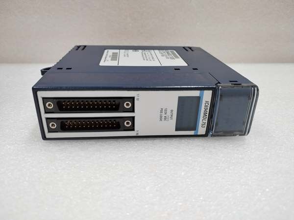
- Output Points: 16 isolated Form A (Normally Open) relay contacts
- Rated Voltage: 5/24/125VDC (nominal), 120/240VAC (nominal)
- Output Voltage Range: 5–125VDC, 5–250VAC (47–63Hz)
- Output Current: 10mA minimum per point; 4A maximum (5–250VAC resistive, 5–30VDC resistive); 200mA maximum at 125VDC; 2A pilot duty/lamp load
- Isolation Rating: 250VAC continuous (field to backplane, point to point); 1500VAC for 1 minute (dielectric withstand)
- Response Time: 10ms maximum (on/off, excluding contact bounce)
- Switching Frequency: 20 cycles per minute maximum
- Contact Life: 200,000 operations at 4A resistive; 700,000 at 1A; 1,000,000 at 0.1A
- Backplane Power Draw: 300mA @ 5VDC (all outputs ON)
- Operating Temperature: 0°C to 60°C (+32°F to +140°F)
- Terminal Block: IC694TBB032 (box-style), IC694TBS032 (spring-style), or extended variants IC694TBB132/IC694TBS132 (sold separately)
- Firmware Requirement: Proficy Machine Edition 5.5 SP2 or later; RX3i CPU Firmware 3.81 or higher
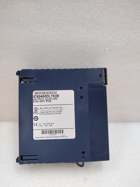
GE IC694MDL753
The Real-World Problem It Solves
When you’re driving a mix of AC and DC loads from the same I/O rack—motor starters at 240VAC, solenoid valves at 24VDC, indicator lamps at 120VAC—you don’t want a single ground fault taking down multiple circuits. The MDL916’s point-to-point isolation means each relay contact is an independent dry contact. No shared commons. No cross-talk. One channel welding shut doesn’t cascade into its neighbor.
Where you’ll typically find it:
- Process skids and package units where field wiring from different vendors lands on the same PLC rack, each with its own power source and grounding scheme
- Motor control centers (MCCs) driving contactor coils across multiple voltage levels (120VAC, 240VAC, 24VDC) from a single module
- Safety-critical shutdown systems where output isolation prevents a single field-side short from affecting multiple shutdown commands
Bottom line: It’s the go-to module when you need flexibility in load voltage and absolute isolation between channels—no shared common, no excuses.
Hardware Architecture & Under-the-Hood Logic
The MDL916 is a passive relay matrix with no onboard microprocessor. It receives 16 discrete output commands from the RX3i CPU over the backplane bus and energizes or de-energizes 16 electromechanical relays accordingly. Each relay is a Form A (single-pole, single-throw, normally open) contact with its own dedicated coil and contact set. No shared commons—the return terminal for each output is isolated from all others.
Internal signal path:
- CPU command → Backplane bus → Module interface circuitry latches 16 output bits
- Driver circuit → Energizes relay coils individually (one coil per point) → Relays close their Form A contacts
- Field power → External AC/DC source → Through closed relay contact → Load
- Diagnostic feedback → Terminal block presence detection, over-temperature sensor → Reported to RX3i CPU (not available on Series 90-30 version IC693MDL916)
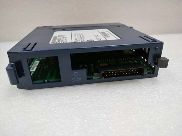
The DIP switch on the module’s rear panel configures the Outputs Default Mode:
- Force Off (switch open/right): All relays de-energize when CPU stops or communication is lost
- Hold Last State (switch closed/left): Relays maintain last commanded state during CPU stop, provided backplane power is present
Note: Hold Last State requires continuous backplane 5VDC power. If backplane power drops, the module defaults to Force Off regardless of DIP switch position.
GE IC694MDL753
Field Service Pitfalls: What Rookies Get Wrong
Hot-Swapping This ModuleThis module does NOT support hot-swap. Pulling it live from a powered rack can arc the backplane connector pins and damage the relay coils. The door card’s red voltage bands are your warning—this is a high-voltage module with no hot-swap rating.
- Field Rule: Power down the rack before removing or inserting MDL916. If hot-swap is mandatory, use IC695MDL series modules instead.
Thermal Derating at Full LoadAt 4A per point, 16 outputs ON, the module dissipates significant heat inside the relay coils. Above 40°C ambient, you cannot have all 16 points ON simultaneously—see the derating curve in GFK-2404A. At 55°C, you’re limited to ~10 outputs ON. Exceed this, and you’ll cook the relay coils or trigger over-temperature faults.
- Field Rule: Count your worst-case simultaneous ON outputs. If you’re in a hot cabinet (>40°C ambient) with 16 outputs at 4A each, derate by reducing channel count or lowering per-point load. Add forced ventilation if the cabinet is sealed.
DIP Switch vs. Software Configuration MismatchThe Outputs Default Mode DIP switch setting MUST match the configuration in Proficy Machine Edition. If they don’t align, the CPU logs a warning in the fault table every time the module powers up. Rookies set the DIP switch and forget to update the software configuration, or vice versa.
- Quick Fix: After installing the module, pull it from the backplane, set the DIP switch (upper switch only—lower switch is unused), re-insert, then open Proficy Machine Edition → Module Configuration → Outputs Default Mode → select “Hold Last State” or “Force Off” to match the hardware setting. Save and download the project.
Inductive Load Contact WeldingDriving contactor coils or solenoid valves without snubbers causes inductive kickback on relay opening, which arcs and welds the contacts over time. The module has no built-in snubber. After 100,000 cycles at 2A inductive load, you’ll start seeing stuck-on outputs.
- Field Rule: For inductive loads (contactor coils, solenoid valves), install external RC snubbers or diodes across the load terminals. For AC inductive loads, use an RC snubber (e.g., 0.1µF + 100Ω); for DC inductive loads, use a flyback diode (reverse-biased across the coil). This extends relay contact life from 200,000 operations to near the mechanical rating.
Commercial Availability & Pricing Note
Please note: The listed price is for reference only and is not binding. Final pricing and terms are subject to negotiation based on current market conditions and availability.


