

Description
Hard-Numbers: Technical Specifications
| Parameter | Value |
|---|---|
| Output Points | 32 discrete outputs (4 isolated groups of 8) |
| Rated Voltage | 12 to 24 VDC (+20%, -15%) |
| Output Voltage Range | 10.2 to 28.8 VDC |
| Output Current | 0.5 A per point, 4 A maximum per group |
| Common Pin Rating | 3 A maximum per group common pin |
| Logic Type | Positive logic (sourcing) |
| Inrush Current | 5.4 A for 10 ms |
| On-State Voltage Drop | 0.3 VDC |
| Off-State Leakage Current | 0.1 mA maximum |
| Response Time | 0.5 ms (both ON and OFF) |
| Power Consumption (Backplane) | 260 mA maximum from 5V bus |
| Power Consumption (User Supply) | 16.5 mA max/group @ 24VDC (all outputs ON)9.6 mA max/group @ 12VDC (all outputs ON) |
| Isolation | Field to Backplane: 250 VAC continuous, 1500 VAC for 1 minuteGroup to Group: 50 VAC continuous, 500 VAC for 1 minute |
| Operating Temperature | 0°C to 60°C (32°F to 140°F) |
| Connector Type | 2x Fujitsu FCN-365P024-AU (24-pin male) |
| LED Indicators | 32 individual status LEDs (one per output) |
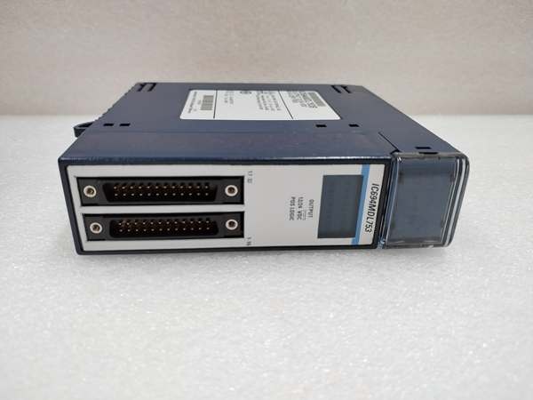
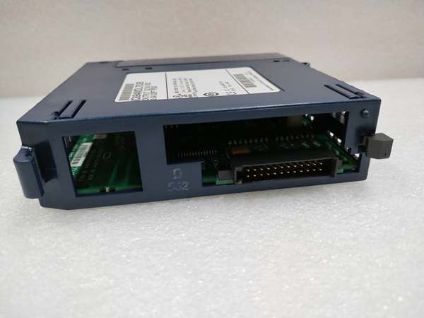
GE IC694MDL753
The Real-World Problem It Solves
This module addresses a common factory floor scenario: you need to drive a large bank of solenoids, indicator lights, or small motor starters from a single I/O slot while maintaining isolation between different voltage domains or load types.
Typical applications include:
- Packaging machines with 24+ pneumatic valve banks
- Assembly line conveyor controls with multiple indicator towers
- Sortation systems requiring high-density output distribution
- Mixed voltage environments (12V and 24V loads from one module)
The four isolated groups give you flexibility. You can wire three groups to your 24V DC supply for valve banks and reserve the fourth group for 12V indicator lights—all from the same module. This saves rack space and reduces wiring complexity compared to using multiple lower-density modules.
The Fujitsu connector design supports pre-wired cables (IC694CBL327, IC694CBL328) or custom field wiring to DIN-rail terminal blocks, making panel build-out faster and more standardized across your facility.
Critical Field Note: All 32 outputs force OFF when the CPU transitions to STOP mode. This is a safety feature, but it can cause process disruptions if you’re expecting outputs to maintain state during PLC program uploads or debugging sessions.
Hardware Architecture & Under-the-Hood Logic
The IC694MDL753B uses positive logic (sourcing) outputs. Current flows from the module output pins through the load to the DC common (negative terminal of your power supply). This is the opposite of negative logic (sinking) modules like the IC694MDL752.
Signal Path:
- CPU writes output state to backplane registers
- Module receives data through high-speed PCI bus (27 MHz)
- Optocouplers isolate field wiring from backplane logic
- MOSFET output drivers switch positive side of load
- External power supply provides current to loads
Power Requirements:
- Backplane: 260 mA from 5V bus powers internal logic and LED indicators
- User Supply: Required for output current. Module draws gate drive current from your 12/24V supply even when outputs are OFF
Group Architecture:Each of the four groups has two common pins (VIN1 through VIN4). Each pin can handle 3A. For group currents between 3A and 4A (rare, but possible with high-density 24V solenoids), you must wire to both VIN pins. This is mandatory—not recommended.
The dual VIN pins also provide redundancy. If one common connection fails due to vibration or terminal creep, the second pin maintains the circuit.
CPU STOP Behavior:Unlike some output modules that offer configurable “hold last state” or “go to defined value” on CPU stop, the MDL753B always forces all outputs OFF. This is hardwired behavior, not configurable through software.
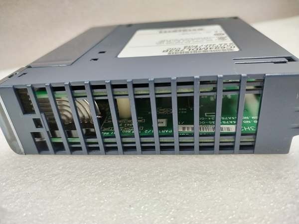
GE IC694MDL753
Field Service Pitfalls: What Rookies Get Wrong
1. Exceeding Group Current Limits
The 4A per group limit is frequently misunderstood. Technicians calculate 0.5A × 8 outputs = 4A and think they’re at the margin. In reality, most 24V solenoid valves draw significantly less than 0.5A (typically 0.15A to 0.3A). The real pitfall is inrush current. If you fire all eight solenoids in a group simultaneously, the 5.4A inrush per output can momentarily exceed 40A total. The module tolerates this for 10ms, but repeated simultaneous firing or inductive kickback from long cable runs can damage the MOSFET drivers.
Field Rule: Stagger outputs if your application allows. If you must fire groups simultaneously, verify inrush current with a current probe and derate accordingly.
2. Neglecting the Dual VIN Pins
The module has two VIN pins per group for a reason. Single-pin wiring is acceptable for low-current applications (<3A total), but in high-density valve manifolds, this is a failure point. I’ve seen installations where vibration caused one common connection to fail intermittently, causing random valve dropouts that technicians blamed on PLC software issues.
Field Rule: Always wire both VIN pins, especially in high-vibration environments (conveyor systems, heavy machinery). It takes 30 seconds extra and prevents hours of troubleshooting.
3. Mixed Voltage Ground Loops
The module supports mixed 12V and 24V loads on different groups, but all groups share the same DC common reference through your power supplies. If you wire Group 1 to a 24V supply with its common tied to earth ground, and Group 4 to a 12V supply with a floating common, you create ground loop paths through the internal MOSFET structures when both groups are active.
Field Rule: Either float all supply commons or tie all supply commons to the same earth ground point. Never mix grounded and floating commons on the same module.
4. Connector Mismatch with Field Wiring
The Fujitsu FCN-365P024-AU connector is not industry-standard. Technicians accustomed to standard terminal blocks sometimes attempt to retrofit generic DIN-rail blocks or Molex connectors. The pin spacing is 5.08mm (0.200 inches), and the housing shape is proprietary. Incorrect mating pins cause contact resistance issues, voltage drop, and potential melting under high current.
Field Rule: Use pre-wired cables (IC694CBL327/IC694CBL328) or build cables with correct Fujitsu mating connectors. Don’t improvise with off-the-shelf terminal blocks.
5. Ignoring Off-State Leakage Current
The 0.1mA off-state leakage current sounds negligible, but with 32 outputs, that’s 3.2mA total. I’ve seen low-current LED indicators glow dimly even when the output is supposedly OFF. In sensitive circuits (optocoupler inputs to other PLCs), this leakage can cause unintended triggering.
Field Rule: For optocoupler-driven inputs, ensure the input threshold is above the leakage voltage. Most industrial optocouplers are fine, but verify with a multimeter if you see ghost activations.
Commercial Availability & Pricing Note
Availability: Active replacement parts available through Emerson Automation channels and authorized distributors.
Pricing: Ranges from 350-750 depending on source, warranty, and condition (new vs. surplus/refurbished).
Important Compatibility Note: The IC694MDL753B is a hardware revision only. Functional specifications, wiring, and configuration are identical to the base IC694MDL753. You can replace an IC694MDL753 with an IC694MDL753B without any software changes, wiring modifications, or parameter reprogramming. The “B” suffix indicates PCB-level or component sourcing changes made during the product lifecycle—likely component availability or manufacturing process improvements. Confirm with your parts vendor if you need original base model for specific certification requirements.
Warranty: New units typically carry 1-2 year manufacturer warranty. Surplus units may have limited or no warranty—verify before purchase.
Commercial Availability Disclaimer: Pricing and inventory data reflect market availability as of 2026 and may vary. This technical document is provided for informational purposes only and does not constitute commercial product endorsement. Verify current specifications, warranty terms, and regulatory compliance directly with Emerson Automation or authorized distributors before procurement decisions.


