
Description
Hard-Numbers: Technical Specifications
- Rated Voltage: 5VDC (TTL mode) and 12-24VDC
- Output Voltage Range: 4.75-5.25VDC (TTL); 10.2-28.8VDC (12/24V mode, +20%, -15%)
- Outputs per Module: 32 points (4 isolated groups of 8)
- Output Current: 25mA/point (TTL mode); 0.5A/point (12/24V mode); 4A max per group; 3A max per common pin
- Response Time: 0.5ms maximum (on and off)
- Inrush Current: 4.6A for 10ms
- On-State Voltage Drop: 0.4VDC max (TTL); 0.24VDC max (12/24V)
- Off-State Leakage: 0.1mA maximum
- Isolation Rating: 250VAC continuous / 1500VAC for 1 minute (field to backplane); 50VAC continuous / 500VAC for 1 minute (group-to-group)
- Power Consumption: 260mA from 5V backplane bus; plus 12-44mA per group from user supply (depends on voltage)
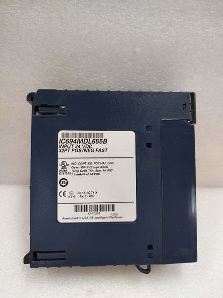
- Operating Temperature: 0°C to +60°C (+32°F to +140°F)
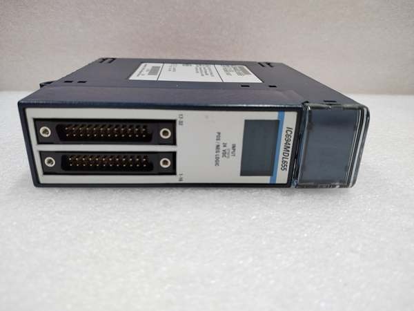
- Connector Type: Two male 24-pin Fujitsu FCN-365P024-AU connectors
- Internal Pull-Up: Each output has internal pull-up resistor to user positive supply
GE IC694MDL655
The Real-World Problem It Solves
Legacy TTL-based control systems – motion controllers, CNC interfaces, servo drives from the 1980s and 1990s – expect active-low signals with internal pull-ups. Standard industrial output modules can’t talk to them without external interface cards or relay racks. The IC694MDL752 bridges that gap by speaking both languages: clean TTL levels for legacy equipment and 0.5A sinking outputs for modern 24VDC devices. One module handles mixed-voltage systems without a drawer full of interface adapters.
Where you’ll typically find it:
- CNC machine retrofit projects where the motion controller still expects TTL-level step/direction signals
- Packaging machinery with legacy servo drives requiring active-low enable and fault signals
- Test stands and calibration fixtures driving 5V logic boards and 24V indicator lamps simultaneously
Bottom line: It’s the translator module for systems caught between the TTL era and the 24VDC world.
Hardware Architecture & Under-the-Hood Logic
The IC694MDL752 is a passive FET switch array – no onboard intelligence. Each output channel is a sinking-type MOSFET that pulls the output pin to common when turned ON (active-low logic). The internal pull-up resistor holds the output HIGH when the FET is OFF, which is what TTL inputs expect. This is opposite to standard sourcing modules that drive outputs HIGH.
Signal flow:
- CPU writes to output image table (%Q memory) via backplane
- Optical isolators translate backplane logic to field-side drive circuits
- When an output is commanded ON, the FET turns ON and sinks current from the load to the group common (active-low: ON = output pulled LOW)
- When OFF, the internal pull-up resistor passively pulls the output to the user supply voltage (typically +5V for TTL or +12/24V for DC mode)
- 32 individual LEDs indicate output status (ON = LED lit = FET conducting = LOW output)
Group isolation architecture:
- Four groups of eight outputs, each with independent common and power input pins
- Each group can be powered from a different voltage source (one group at 5V for TTL, three groups at 24V for industrial loads)
- Group-to-group isolation is only 50VAC continuous – do not mix vastly different voltage potentials between groups
GE IC694MDL655
Field Service Pitfalls: What Rookies Get Wrong
Active-Low Logic Confuses Everyone
This module is negative logic (sinking). When you command an output ON, the output pin goes LOW (near 0V), not HIGH. The LED lights up when the output is LOW. I’ve watched techs troubleshoot for hours because they expected +24V at the output when the LED was on – they were reading it backward.
- Field Rule: With a multimeter, measure between the output pin and DC+. When the output is ON, you should read near the supply voltage (because the output is sinking to common). When OFF, you read near 0V (because the pull-up holds it at DC+).
TTL Mode vs. 12/24V Mode – Know Which You’re In
The module doesn’t auto-detect voltage mode. You configure it by how you wire the user supply. If you connect +5V to a group’s VIN pin, that group operates in TTL mode (25mA max). If you connect +12V or +24V, it operates in DC mode (0.5A max). Rookie mistake: wiring 24V to a group and expecting 25mA current limiting – it won’t trip at 25mA, it’ll let you pull 500mA and cook your TTL device.
- Quick Fix: Check the VIN voltage for each group before connecting loads. If it’s +5V, treat it as TTL only. If it’s +12/24V, you have 0.5A capacity but no current limiting.
Group-to-Group Isolation Is Weak
50VAC continuous isolation between groups means you cannot wire one group at 120VAC-referenced potential and another at ground. I’ve seen designs that put group 1 on a floating 24V supply referenced to AC neutral, and group 2 on a grounded 24V supply – that 50V isolation limit gets exceeded during ground faults.
- Field Rule: Keep all groups on the same ground reference. If you need true galvanic isolation between voltage domains, use separate modules, not separate groups on one MDL752.
Connector Headaches
The module uses Fujitsu FCN-365P024-AU connectors, not standard screw terminals. You need pre-wired cables (IC694CBL327/IC694CBL328) or custom cables with the right female connector. Techs on site often don’t have these cables and try to improvise – which leads to intermittent connections and pulled wires.
- Quick Fix: Stock at least two sets of IC694CBL327/328 cables in the maintenance crib. If you’re building custom cables, buy the proper female connectors (Fujitsu FCN-365C024-AU) – don’t try to solder directly to the male pins.
No Fault Diagnostics
This module reports no faults to the CPU. If a output FET fails shorted, the LED stays lit and the output stays LOW – the CPU thinks everything is fine. If a FET fails open, the LED won’t light but the output will be stuck HIGH. No alarm, no fault bit.
- Field Rule: For critical outputs, use external feedback (wire a spare input to monitor the output state) or upgrade to a module with fault diagnostics like the MDL754.
Commercial Availability & Pricing Note
Please note: The listed price is for reference only and is not binding. Final pricing and terms are subject to negotiation based on current market conditions and availability.


